Phosphate rock scrubbing of a sulfur dixoide gas stream

Inactive Publication Date: 2019-11-07
CLARK SOLUTIONS LLC
View PDF0 Cites 3 Cited by
  • Summary
  • Abstract
  • Description
  • Claims
  • Application Information

AI Technical Summary

Benefits of technology

[0010]Although the patent literature is full of examples whereby either an inorganic or organic base is used to scrub a gas stream and thereby achieving extremely low levels of sulfur dioxide, the simple fact is th

Problems solved by technology

Although the patent literature is full of examples whereby either an inorganic or organic base is used to scrub a gas stream and

Method used


Image

  • Phosphate rock scrubbing of a sulfur dixoide gas stream
  • Phosphate rock scrubbing of a sulfur dixoide gas stream
  • Phosphate rock scrubbing of a sulfur dixoide gas stream

Examples


Embodiment Construction

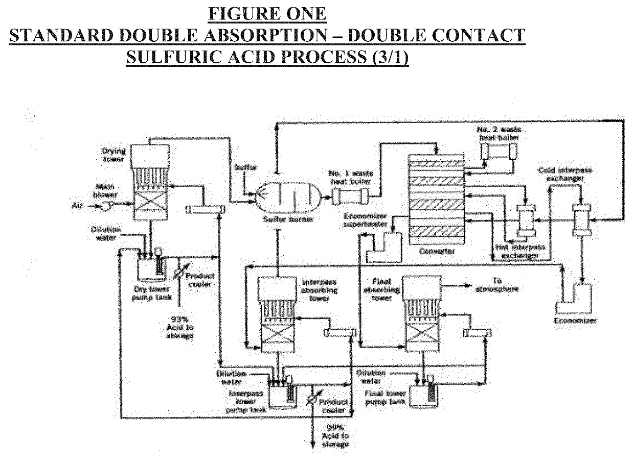
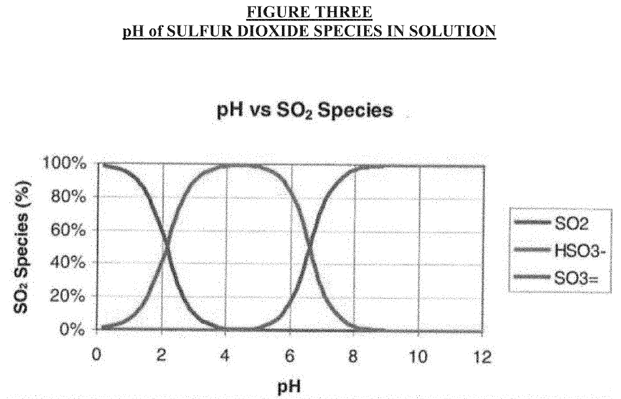
[0024]A phosphate rock solution with a pH>3 and preferably less than 10 to avoid unnecessary carbon dioxide pickup is added in a scrubber circulating system with pumps, holding tanks, level indicators and the needed equipment to run a scrubber. Fresh phosphate rock solution is continually added to maintain this pH, as well known in the scrubbing industry. Level control continually draws off the sulfur dioxide enriched solution, which is fed into a Phosphate Rock Acidifier which is used in the phosphate fertilizer presently. The pH of that contactor is maintained at ˜1 to ensure that other stronger acids (such as the halides—chlorides. fluorides, and bromides) do not spring free. Any dissolved carbon dioxide will also be present with the sulfur dioxide stream, but this presents very little problem in contact sulfuric acid plants. The highly purified SO2 enriched which is saturated with water vapor then enters a little SO2 drying tower and blower which boosts the gas pressure to just ...


PUM

PropertyMeasurementUnit
Purityaaaaaaaaaa

Abstract

This application is directed to the field of scrubbing a sulfur dioxide-laden gas stream by a phosphate rock solution, and then regenerating that sulfur dioxide gas via acidulation, by contacting the phosphate rock solution with sulfuric acid to regenerate a high purity sulfur dioxide stream.

Description

CROSS REFERENCE TO RELATED APPLICATIONS[0001]This application claims the benefit of U.S. Application No. 62 / 661,433, filed Apr. 23, 2018. The contents of U.S. Application No. 62 / 661,433, filed Apr. 23, 2018 are incorporated by reference in its entirety.FIELD OF INVENTION[0002]This application is directed to the field of scrubbing a sulfur dioxide-laden gas stream by a phosphate rock solution, and then regenerating that sulfur dioxide gas via acidulation, by contacting the phosphate rock solution with sulfuric acid to regenerate a high purity sulfur dioxide stream.BACKGROUND OF INVENTION[0003]Since the passage of the Clean Air Act in 1973, the United States Environmental Protection Agency has mandated sulfur dioxide conversion levels of 99.7% (or 4 pounds of sulfur dioxide emitted per Short Ton of sulfuric acid produced). A typical flow diagram showing all the gas-side equipment for a Double Contact Double Absorption (DC / DA) sulfuric acid plant is shown in Figure One, employing a 3 / 1...

Claims


Application Information

Patent Timeline
IPC IPC(8): B01D53/50B01D53/80B01D53/96C01B17/04
CPCB01D53/507B01D2257/302B01D53/80C01B17/0404B01D53/96B01D2251/61B01D53/78B01D2258/0283
Inventor BURMASTER, BRIAN M.
Owner CLARK SOLUTIONS LLC
Why Eureka
Try Eureka