Method for manufacture of gray cast iron for crankcases and cylinder heads

a technology of crankcases and cylinder heads, which is applied in the direction of cylinders, machines/engines, mechanical equipment, etc., can solve the problems of poor cutting tool life and performance, poor machining performance, damaged castings, etc., and achieves the effects of reducing phosphorus levels, reducing carbon levels, and improving machining efficiency

Inactive Publication Date: 2005-12-13
INT ENGINE INTPROP CO LLC
View PDF9 Cites 5 Cited by
  • Summary
  • Abstract
  • Description
  • Claims
  • Application Information

AI Technical Summary

Benefits of technology

[0007]In this method of manufacture, the molten gray iron metal has, compared with prior manufacturing methods, substantially increased carbon levels, lower levels of phosphorus, significantly lower levels of chromium, somewhat lower levels of sulfur, and, with the alloying use of tin as a pearlite stabilizer, substantially reduces the potential for iron carbide hard spots and chills, and allows significantly reduced silicon content in the gray iron and minimal inoculant additions. Further, the high shake-out temperatures for the resulting castings also minimizes the need for alloy addition and provides castings with lower residual stresses.

Problems solved by technology

Notwithstanding this prior work, in order to meet strength requirements, gray iron castings for crank cases and cylinder heads were manufactured by alloying molten gray iron with chromium, but this caused hard spots in the casting due to chilling and iron carbide formation, which resulted in machining difficulties, damaged castings, and poor cutting-tool life and performance.
In an effort to partially reduce the chilling tendency, silicon levels in the gray iron base and additions of a silicon-based inoculant were increased in the molten gray iron, which significantly increased the cost of manufacture.
Furthermore, the additional silicon increased the need for a chromium strengthening alloy, which further increased costs and the tendency to form iron carbide hard spots and chills.
In addition, as a result of the high level of alloying, solidification stresses in the resulting crank cases and cylinder heads were high, requiring stress relief heat treatment to minimize distortion and cracking of the castings during processing.

Method used


Image

  • Method for manufacture of gray cast iron for crankcases and cylinder heads
  • Method for manufacture of gray cast iron for crankcases and cylinder heads

Examples


Embodiment Construction

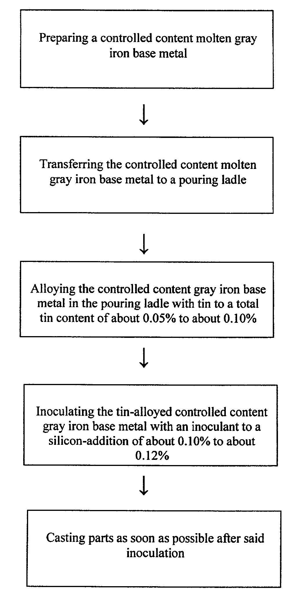
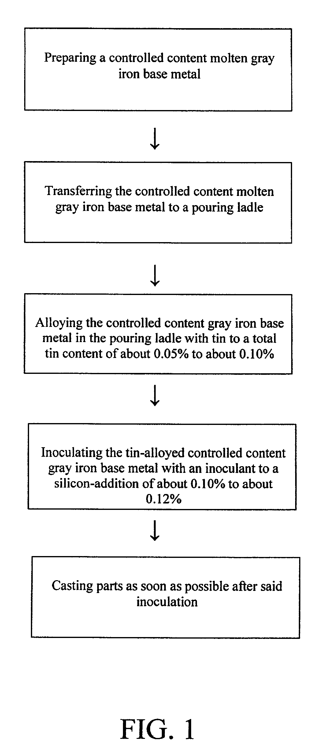
[0010]As illustrated in FIG. 1, the first step in the method of the invention is preparing a molten gray iron base metal having a controlled content. The molten gray iron metal is prepared in an electric furnace from scrap steel, gray iron ingots, and gray iron scrap recovered from the manufacturing process. The content of the molten gray iron metal is controlled by making spectrographic analyses of the scrap steel, gray iron ingots, and recovered gray iron scrap, adjusting the relative amounts of each of these three ingredients and, to the extent necessary, and supplementing the molten gray iron by the addition of one or more of silicon, phosphorus, manganese and chromium, as needed. Because of the general low levels of phosphorus, sulfur and chromium to be maintained in the molten gray iron metal, reduced amounts of these alloying metals are necessary, if any.

[0011]In the second step, the controlled content molten grey iron metal is placed in a pouring ladle for further processing...


PUM

PropertyMeasurementUnit
temperatureaaaaaaaaaa
temperaturesaaaaaaaaaa

Abstract

A method of casting parts with gray iron includes the steps of providing molten gray iron metal with controlled carbon, silicon, phosphorous, sulfur, manganese and chromium content; alloying said molten gray iron metal, prior to pouring, with tin to a total tin content of about 0.05% to about 0.10%; inoculating said molten tin-alloyed gray iron metal, prior to pouring, with a gray iron inoculant to an additional silicon addition of from about 0.10% to about 0.12%; and casting the gray iron part from said molten, tin-alloyed inoculated gray iron metal as son as possible after said inoculation.

Description

FIELD OF THE INVENTION[0001]This invention relates to casting methods using gray cast iron, and more particularly to casting methods for the manufacture of crank cases and cylinder heads with gray cast iron.BACKGROUND OF THE INVENTION[0002]Gray iron is a desirable casting material because its excellent castability and low cost makes it versatile for the manufacture of products such as crank cases and cylinder heads. Such manufacturing components require high strength, soundness, good machinability, dimension stability and uniform properties. To obtain these qualities, it is important to achieve a uniform metallurgical structure throughout all sections of the casting and particularly a uniform pearlite structure. Alloys are commonly added to gray cast iron materials in the casting process in an effort to achieve these desirable properties, and the effect of alloying on gray iron has been extensively studied, as indicated, for example, by “A Modern Approach To Alloying Gray Iron,” Jan...

Claims


Application Information

Patent Timeline
Patent Type & Authority Patents(United States)
IPC IPC(8): F02F1/00B22D1/00C21C1/08C22C33/08C22C37/06C22C37/10F02F1/24F02F7/00
CPCC21C1/08C22C33/08C22C37/10F02F7/0085F05C2201/0439B22D27/00C22C37/06F02F7/00
Inventor WARD, JOSEPH R.
Owner INT ENGINE INTPROP CO LLC
Why Eureka
Try Eureka