Pipelayer machine having hoisting system with pivotable fairlead

a technology of hoisting system and pipelayer machine, which is applied in the direction of hoisting equipment, load-engaging elements, safety gear, etc., can solve the problems of challenging the industry, unable to stably support suspended loads, and particularly acute challenges

Active Publication Date: 2019-11-07
CATERPILLAR INC
View PDF30 Cites 16 Cited by
  • Summary
  • Abstract
  • Description
  • Claims
  • Application Information

AI Technical Summary

Benefits of technology

[0004]In one aspect, a fairlead for a hoisting system in a ground-engaging machine includes a fairlead base for coupling to a frame of the ground-engaging machine, a fairlead boom, and a pivot joint pivotably coupling the fairlead boom to the fairlead base. The fairlead further includes a plurality of feed pullies mounted ...

Problems solved by technology

Due to the nature of pipeline placement and support of pipe sections out to the side of the machine, there can be challenges to stably supporting the suspended load without risking tipping the machine.
These chall...

Method used


Image

  • Pipelayer machine having hoisting system with pivotable fairlead
  • Pipelayer machine having hoisting system with pivotable fairlead
  • Pipelayer machine having hoisting system with pivotable fairlead

Examples


Embodiment Construction

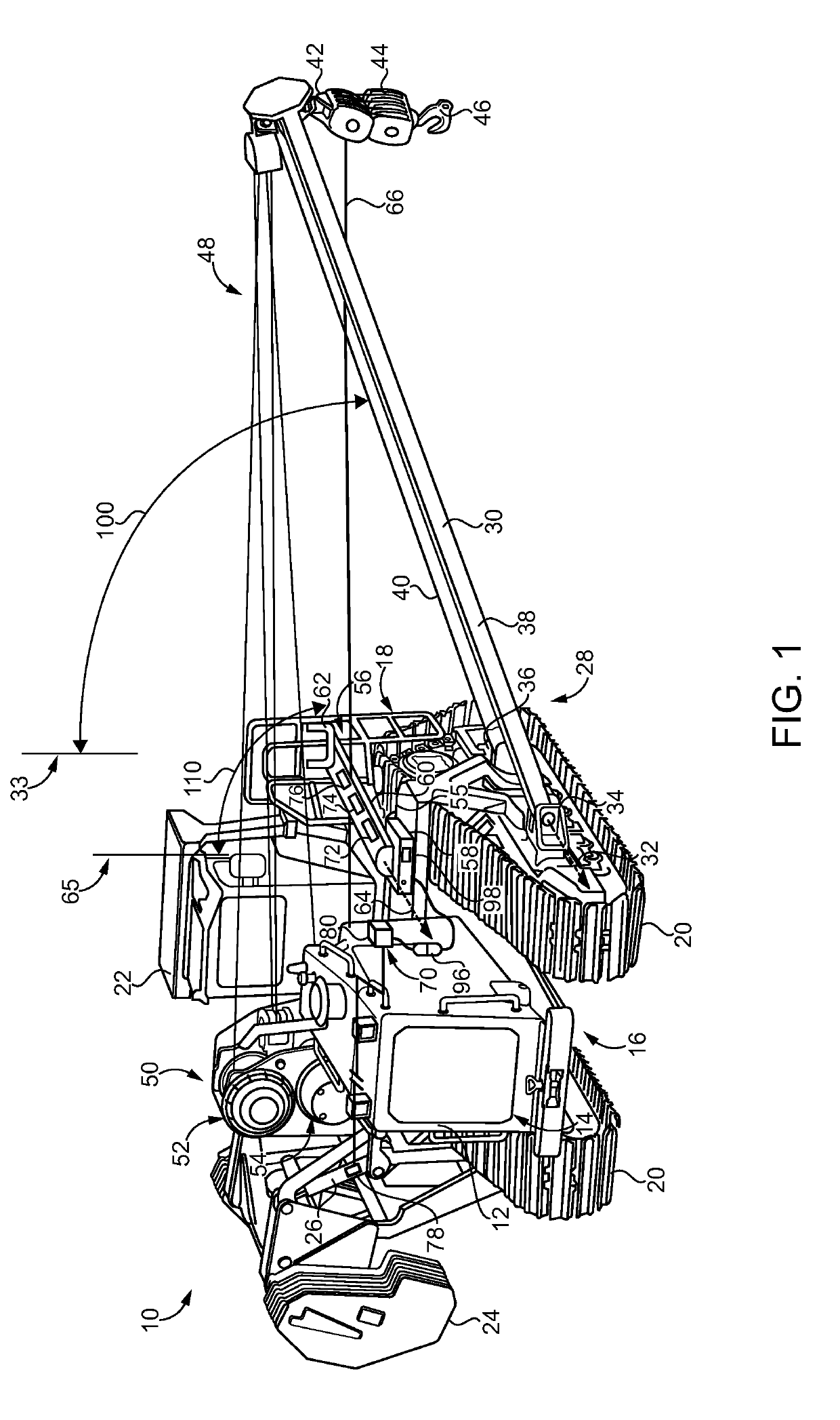
[0014]Referring to FIG. 1, there is shown a ground-engaging machine 10 according to one embodiment, and structured as a pipelayer machine for transporting, suspending, and placing pipe sections of a pipeline according to generally known practices. Machine 10 includes a frame 12 having a front frame end 16 and a back frame end 18. An engine system 14 is mounted adjacent to front frame end 16 in the illustrated embodiment. An operator station 22 is coupled to and mounted upon frame 12 between front frame end 16 and back frame end 18. Operator station 22 can include an operator cab. Ground-engaging elements 20, including tracks in the illustrated embodiment, are coupled to and positioned upon opposite sides of frame 12. Machine 10 further includes a counterweight 24 positioned upon one side of frame 12 and adjustable by way of one or more counterweight actuators 26 in a generally conventional manner.

[0015]Machine 10 also includes a hoisting system 28 having a sideboom 30 movable by piv...


PUM


Abstract

A machine includes a frame, ground-engaging elements coupled to the frame, and a hoisting system having a sideboom and a fairlead. The hoisting system also includes a hook pulley block and a hoisting cable extending through the fairlead and the hook pulley block and held in tension such that the hoisting cable couples pivoting of the fairlead to pivoting of the sideboom. The pivotable fairlead may be instrumented with position, cable loading, and cable feed sensors.

Description

TECHNICAL FIELD[0001]The present disclosure relates generally to a machine equipped with a sideboom and fairlead for guiding a hoisting cable to and from the sideboom, and more particularly to such a machine where the fairlead is pivotable.BACKGROUND[0002]Pipelayers are specialized machines used to suspend and place pipelines in a prepared trench or the like. A typical pipelayer includes a load manipulating boom that projects outwardly from the side of the machine in a direction generally perpendicular to a forward travel direction. It is common for a cable and rigging system to be provided for manipulating the position of the boom, as well as a load suspended by the boom adjacent to or within a trench. It is also typical for pipelayers to operate in teams with a group of the machines operating in a coordinated fashion, to each support a different section of pipe as the pipe is gradually placed into a trench. In some instances the pipe sections are welded together as they are suspen...

Claims


Application Information

Patent Timeline
IPC IPC(8): B66C23/62B66D1/36B66C23/44B66D1/00B66D1/48B66D1/54B66C15/06
CPCB66D1/54B66C23/44B66D1/48B66C15/065B66C2700/0357B66D1/36B66D2700/0191B66C23/62B66D1/00
Inventor FANELLO, SHAWN PHILIPCAMACHO, TIMOTHY EDWARD
Owner CATERPILLAR INC
Why Eureka
Try Eureka