Water-cooling head

a water-cooling head and water-cooling head technology, which is applied in the direction of liquid fuel engines, light and heating apparatus, machines/engines, etc., can solve the problems of increasing the structural complexity occupying the inner space and difficulty in flow of working medium, so as to improve the heat dissipation performance simplify the internal structure of the water-cooling head. , the effect o

Active Publication Date: 2019-11-07
AURAS TECH
View PDF4 Cites 6 Cited by
  • Summary
  • Abstract
  • Description
  • Claims
  • Application Information

AI Technical Summary

Benefits of technology

[0005]For solving the drawbacks of the conventional technologies, the present invention provides a water-cooling head. The structure of an impeller of the water-cooling head is specially designed to inhale and guide the working medium within an active space to flow. Consequently, the internal structure of the water-cooling head is simplified, the volume of the water-cooling head is reduced, and the heat dissipating performance of the water-cooling head is enhanced.
[0024]In accordance with another aspect of the present invention, there is provided a water-cooling head. The water-cooling head includes an active space and an impeller. The active space includes a heat-absorbing space and a drainage space. A working medium is filled in the active space. The impeller is disposed within the active space, and includes a seat part and a hollow part. The active space is divided into the heat-absorbing space and the drainage space by the seat part. The working medium within the heat-absorbing space and the drainage space undergoes a fluidly coupling effect through the hollow part.
[0033]From the above descriptions, the structure of the impeller of the water-cooling head is specially designed to inhale and guide the working medium within an active space to flow. Consequently, the internal structure of the water-cooling head is simplified, the volume of the water-cooling head is reduced, and the heat dissipating performance of the water-cooling head is enhanced.

Problems solved by technology

However, it is difficult to flow the working medium by using the impeller of the pump only.
However, too many guiding structures may increase the structural complexity of the water-cooling head, occupy the inner space of the water-cooling head and increase the fabricating cost.
Moreover, since the inner space of the water-cooling head is largely occupied by the guiding structures, the overall height of the water-cooling head cannot be reduced.

Method used


Image

  • Water-cooling head
  • Water-cooling head
  • Water-cooling head

Examples


Embodiment Construction

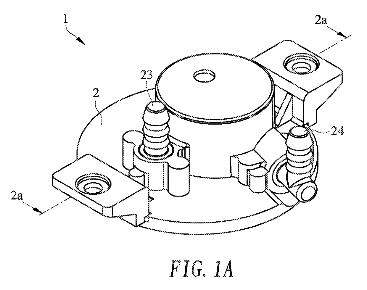
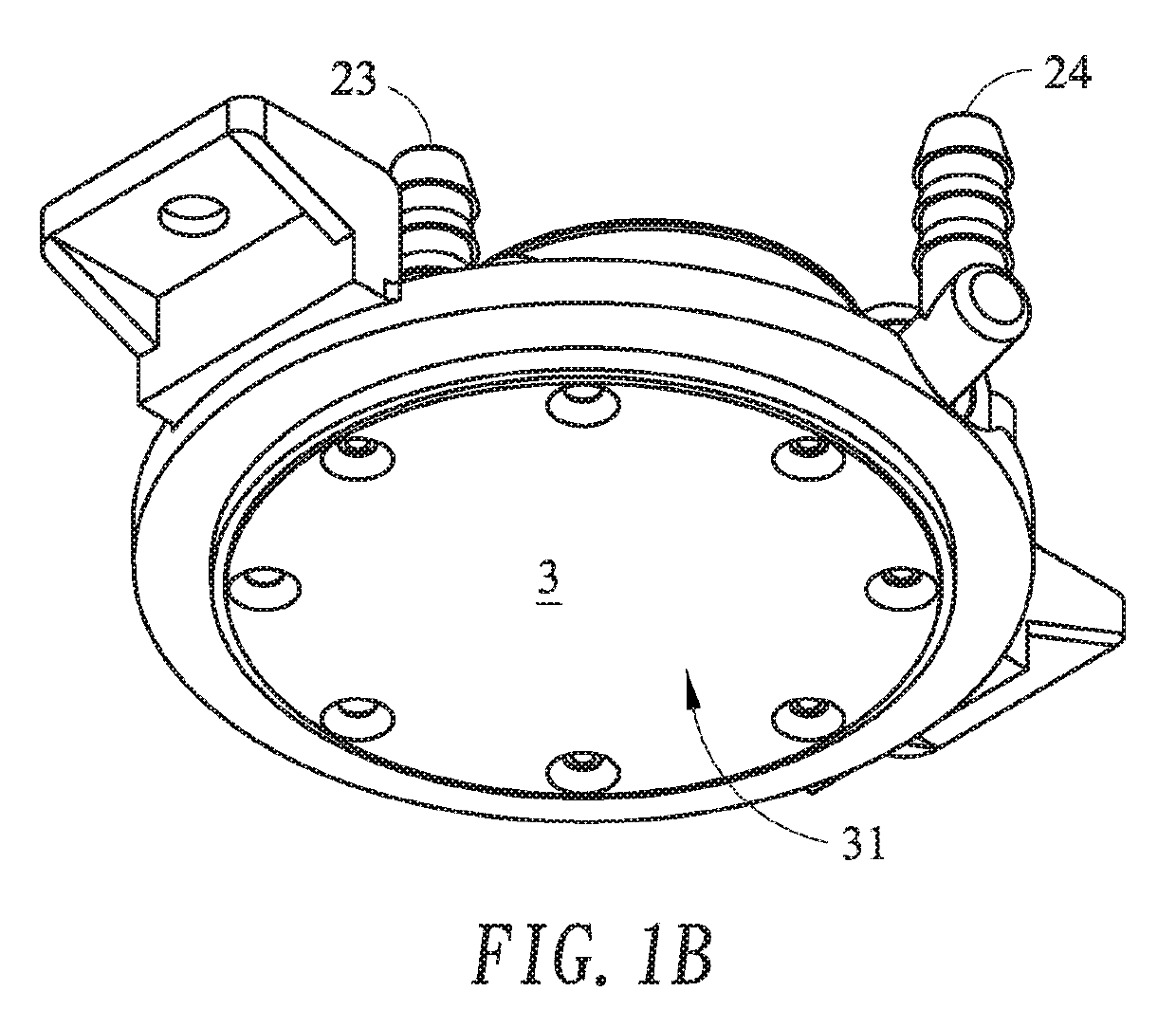
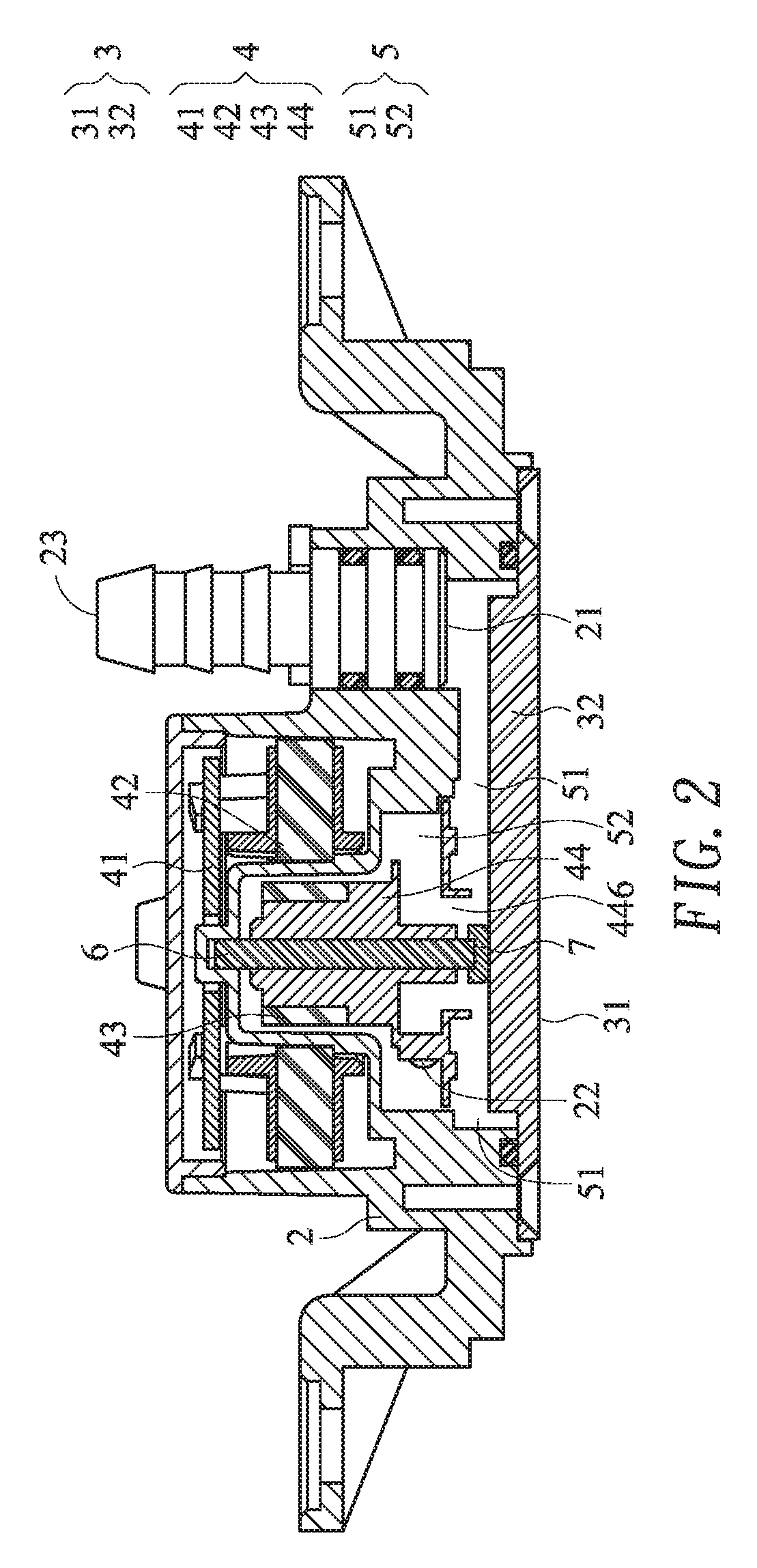
[0049]The present invention provides a water-cooling head with a built-in pump. Please refer to FIGS. 1A, 1B, 2 and 3. The water-cooling head 1 comprises a casing 2, a base 3 and a pump 4. The casing 2 and the base 3 are combined together through a screwing means or any other appropriate fixing means. Consequently, an active space 5 for allowing a working medium to go through is defined by the casing 2 and the base 3 collaboratively. After the working medium is filled into the active space 5 by the user or the manufacturer, the heat dissipating function of the water-cooling head 1 is achieved.

[0050]The casing 2 comprises an input channel 21 and an output channel 22. The input channel 21 is in communication with the active space 5. The cooled working medium is introduced into the active space 5 through the input channel 21. The output channel 22 is also in communication with the active space 5. The heated working medium is outputted from the active space 5 through the output channel ...


PUM


Abstract

A water-cooling head includes a casing, a base, an input channel, an output channel and a pump. An active space is defined by the base and the casing collaboratively. A working medium is filled in the active space. The heat absorbed by the base is transferred to the working medium. The input channel is in communication with the active space. The cooled working medium is introduced into the active space through the input channel. The output channel is in communication with the active space. The heated working medium is outputted from the active space through the output channel. The pump is installed on the casing, and includes an impeller. The impeller is disposed within the active space and located near the output channel. The impeller is driven to guide the working medium to be outputted from the active space through the output channel.

Description

CROSS-REFERENCE TO RELATED APPLICATION[0001]This application claims priority to U.S. Provisional Patent Application No. 62 / 666,733 filed Mar. 4, 2018, the contents of which are incorporated herein by reference.FIELD OF THE INVENTION[0002]The present invention relates to a heat dissipation module, and more particularly to a water-cooling head.BACKGROUND OF THE INVENTION[0003]Nowadays, a water-cooling head with a built-in pump has been introduced into the market. However, it is difficult to flow the working medium by using the impeller of the pump only. For stably transferring the working medium along a one-direction circular loop, the casing or the inner structure of the water-cooling head is equipped with plural guiding structures for assisting the impeller of the pump. For example, in U.S. Pat. No. 8,245,764, an impeller cover, an intermediate member and the connected passages are used as the guiding structures of the water-cooling head to separate the inner portion of the water-co...

Claims


Application Information

Patent Timeline
Patent Type & Authority Applications(United States)
IPC IPC(8): F28F3/12F04D1/04F04D29/24F04D29/20F28F9/02
CPCF28F9/0246F04D29/20F04D1/04F28F2250/08F28F3/12F04D29/24F04D29/5893F04D29/2266F04D29/167H01L23/473F28D2001/0253H05K7/20272F28D1/0233F04D29/266H05K7/20263H05K7/20218
Inventor CHEN, CHIEN-ANFAN, MU-SHUCHEN, CHIEN-YU
Owner AURAS TECH
Why Eureka
Try Eureka