Infrared imaging systems and methods for oil leak detection

a technology of infrared imaging and oil leak detection, applied in the field of systems and methods for detecting oil on surfaces, can solve problems such as oil leakage, oil loss, and oil leakage in any componen

Active Publication Date: 2019-11-07
QUANTUM IR TECH LLC
View PDF12 Cites 19 Cited by
  • Summary
  • Abstract
  • Description
  • Claims
  • Application Information

AI Technical Summary

Benefits of technology

[0005]In some embodiments, a system for detecting an oil leak can include: at least one infrared imaging sensor; and an imaging analysis computer operably coupled with the at least one infrared imaging sensor. The imaging analysis computer can be configured to control any infrared imaging sensor and acquire infrared images therefrom at any rate and in any duration. The imaging analysis computer can be configured to analyze the infrared images in order to detect an oil leak. The imaging analysis computer can be configured to detect oil on a surface where oil should not be (or is not present in a baseline) in order to determine that there is an oil leak in the vicinity.

Problems solved by technology

Generally, it is problematic to have a petroleum fluid, such as oil, on any environmental surface or industrial surfaces where it does not belong.
Leaks can occur in any component that stores or transports oil, which mandates oil leak detection.
Loss of oil from leaks also leaves a financial toll on the refinery.

Method used


Image

  • Infrared imaging systems and methods for oil leak detection
  • Infrared imaging systems and methods for oil leak detection
  • Infrared imaging systems and methods for oil leak detection

Examples


Embodiment Construction

[0036]In the following detailed description, reference is made to the accompanying drawings, which form a part hereof. In the drawings, similar symbols typically identify similar components, unless context dictates otherwise. The illustrative embodiments described in the detailed description, drawings, and claims are not meant to be limiting. Other embodiments may be utilized, and other changes may be made, without departing from the spirit or scope of the subject matter presented herein. It will be readily understood that the aspects of the present disclosure, as generally described herein, and illustrated in the figures, can be arranged, substituted, combined, separated, and designed in a wide variety of different configurations, all of which are explicitly contemplated herein.

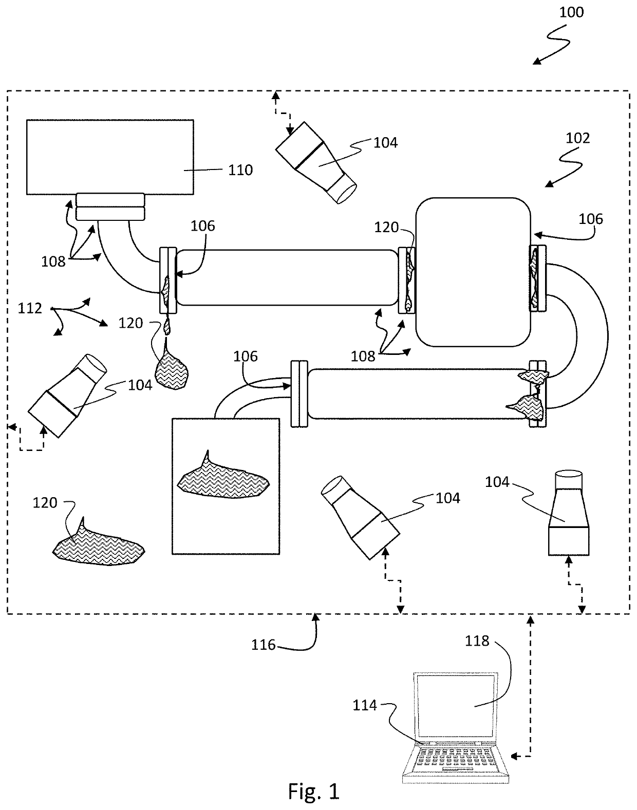
[0037]Generally, the present technology provides a system and method for detecting an oil leak that can include at least one infrared imaging sensor and an imaging analysis computer operably coupled with the...


PUM


Abstract

A system for detecting an oil leak can include: at least one infrared imaging sensor; and an imaging analysis computer operably coupled with the at least one infrared imaging sensor. The imaging analysis computer can be configured to control any infrared imaging sensor and acquire infrared images therefrom at any rate and in any duration. The imaging analysis computer can be configured to analyze the infrared images in order to detect an oil leak. The imaging analysis computer can be configured to detect oil on a surface (e.g., solid surface or water surface) where oil should not be (or is not present in a baseline) in order to determine that there is an oil leak in the vicinity.

Description

CROSS-REFERENCE[0001]This patent application claims priority to U.S. Provisional Application No. 62 / 666,610 filed May 3, 2018, which provisional is incorporated herein by specific reference in its entirety.BACKGROUNDField[0002]The present invention relates to systems and methods for detecting oil on surfaces. In some aspects, the present invention relates to infrared imaging systems and methods for detecting oil on solid surfaces or water surfaces.Description of Related Art[0003]Generally, it is problematic to have a petroleum fluid, such as oil, on any environmental surface or industrial surfaces where it does not belong. Leaks can occur in any component that stores or transports oil, which mandates oil leak detection. Environmental damage can be reduced or prevented with faster oil leak detection. Loss of oil from leaks also leaves a financial toll on the refinery. As a result, improvements in oil leak detection can be good for the environment and for reducing refinery or other fa...

Claims


Application Information

Patent Timeline
Patent Type & Authority Applications(United States)
IPC IPC(8): G01M3/38G06T7/00G06T7/11G06T7/174H04N5/33G01J5/52G01J5/54
CPCH04N5/33G06T7/174G06T7/11G01M3/38G01J5/522G01J2005/0077G01J5/54G06T2207/10048G06T7/001G01J5/0066G01J5/0295G01M3/002G01J5/48G01J5/53
Inventor ISRAELSEN, MARK
Owner QUANTUM IR TECH LLC
Why Eureka
Try Eureka