Backlight module and LCD device

a backlight module and liquid crystal display technology, applied in the field of display technology, can solve the problems of severe light leakage, low light coupling efficiencyaffecting the performance of the device, etc., and achieve the effects of reducing the leakage of the backlight module, enhancing light utilization efficiency, and enhancing light coupling efficiency

Active Publication Date: 2019-11-07
HUIZHOU CHINA STAR OPTOELECTRONICS TECHNOLOGY CO LTD
View PDF17 Cites 1 Cited by
  • Summary
  • Abstract
  • Description
  • Claims
  • Application Information

AI Technical Summary

Benefits of technology

[0017]The advantages of the present invention are as follows. The backlight module includes a light guide plate and a light source located at a distance to a side of the light guide plate. The light source includes a substrate, multiple LED chips disposed on the substrate, multiple primary lenses disposed on the substrate corresponding to the LED chips, and multiple condenser lenses disposed on the substrate corresponding to the primary lenses. Each primary lens is disposed correspondingly to a LED chip,

Problems solved by technology

TFTs directly affect the performance of these devices.
When these LEDs are inserted unto printed circuit boards (PCBs), due to the precision of the workstation, some LEDs are not aligned and some have their light emission face above the LGP, causing severe light leakage.
The backlight module t

Method used


Image

  • Backlight module and LCD device
  • Backlight module and LCD device

Examples


Embodiment Construction

[0021]The following descriptions for the respective embodiments are specific embodiments capable of being implemented for illustrations of the present invention with referring to appended figures.

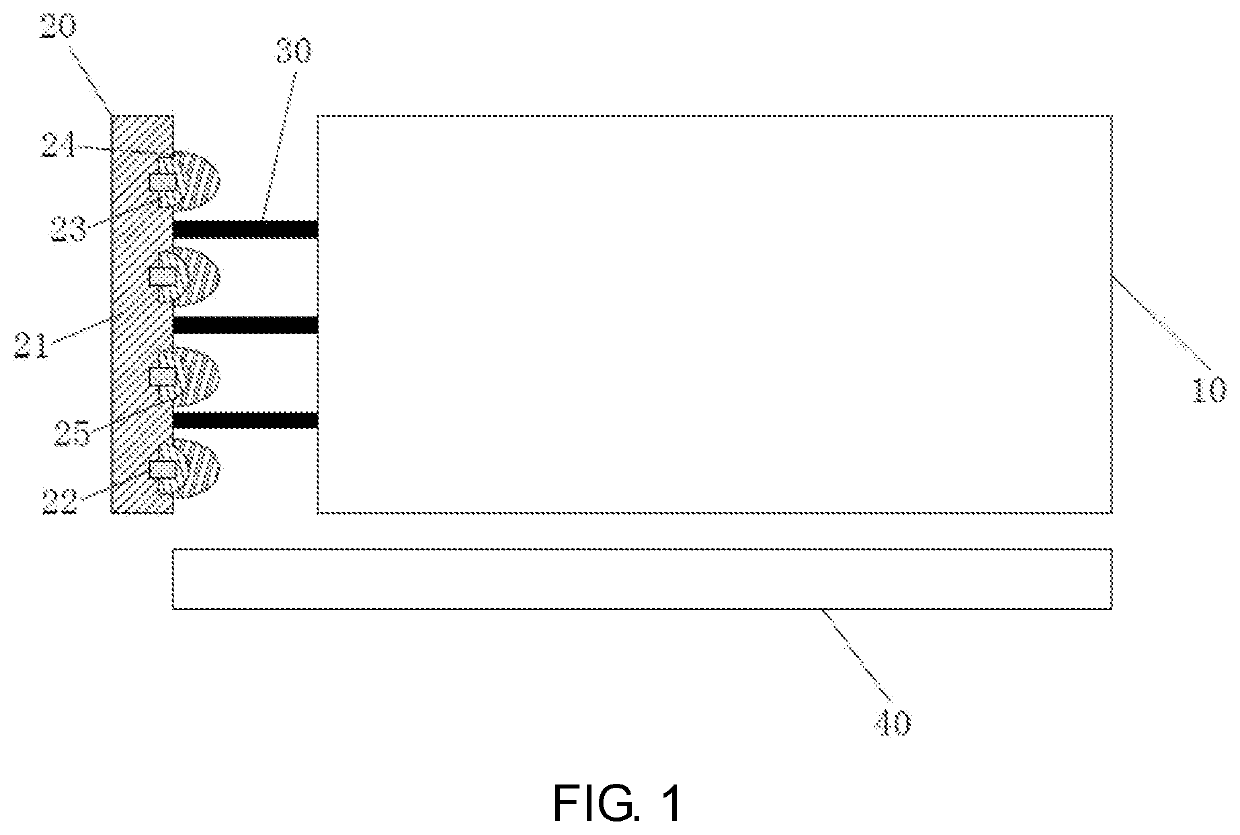
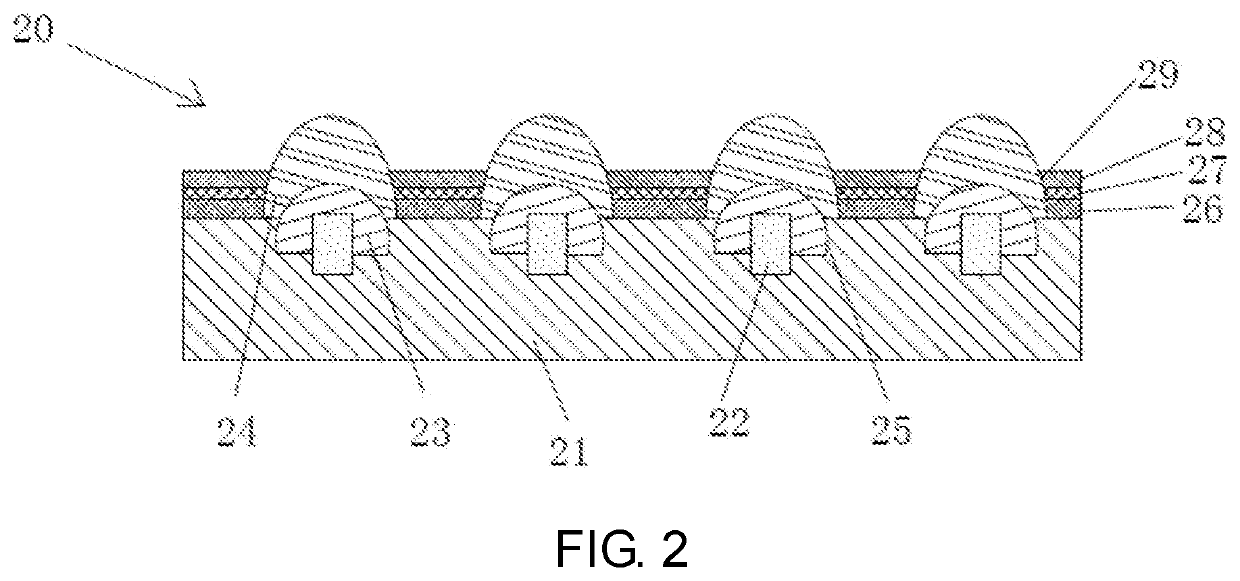
[0022]As shown in FIG. 1, a backlight module according to an embodiment of the present invention includes a light guide plate 10, and a light source 20 located at a distance to a side of the light guide plate 10. The light source 20 includes a substrate 21, multiple LED chips 22 disposed on the substrate 21, multiple primary lenses 23 disposed on the substrate 21 corresponding to the LED chips 22, and multiple condenser lenses 24 disposed on the substrate 21 corresponding to the primary lenses 23.

[0023]It should be noted that, for the multiple primary lenses 23 corresponding to the multiple LED chips 22, each primary lens 23 is disposed correspondingly to a LED chip 22, focuses light from the LED chip 22, and prevents the light emission face of the LED chip 22 from being higher above the li...


PUM


Abstract

The present invention teaches a backlight module and the LCD device. The backlight module includes a light guide plate and a light source located at a distance to a side of the light guide plate. The light source includes a substrate, multiple LED chips disposed on the substrate, multiple primary lenses disposed on the substrate corresponding to the LED chips, and multiple condenser lenses disposed on the substrate corresponding to the primary lenses. Each primary lens is disposed correspondingly to a LED chip, focuses light from the LED chip, and prevents the light emission face of the LED chip from being higher above the light guide plate, thereby enhancing the light coupling efficiency and reducing leakage of the backlight module. Each condenser lens is disposed correspondingly to a primary lens to further narrow light emission angle of the LED chip, enhancing light utilization efficiency.

Description

FIELD OF THE INVENTION[0001]The present invention is generally related to the field of display technology, and more particularly to a backlight module and a liquid crystal display (LCD) device.BACKGROUND OF THE INVENTION[0002]Thin film transistors (TFTs) are the major driving components in existing LCD devices and active matrix organic light-emitting diode (AMOLED) devices. TFTs directly affect the performance of these devices.[0003]Existing LCD devices are usually back-lighted display devices, and include a LCD panel and a backlight module. The principle behind a LCD panel is to fill liquid crystal molecules between a TFT array substrate and a color filter (CF) substrate, and to alter the alignment of the liquid crystal molecules by the electrical field formed between the substrates as the substrates are applied with pixel and common voltages. As such, light from the backlight module is refracted to produce images.[0004]Ultra-thin LCD devices are currently the mainstream product, a...

Claims


Application Information

Patent Timeline
IPC IPC(8): F21V8/00G02F1/13357
CPCG02B6/003G02B6/0055G02F1/1336G02B6/0073G02B6/0068G02B6/0013
Inventor FAN, YONGHSIAO, YUCHUN
Owner HUIZHOU CHINA STAR OPTOELECTRONICS TECHNOLOGY CO LTD
Why Eureka
Try Eureka