Liquid Crystal Display Device And Backlight Module

a backlight module and display device technology, applied in the field of liquid crystal display techniques, can solve the problems of reducing warping unable to achieve the brightness increase required by conventional edge lit techniques along a single longer edge of the light guide plate, so as to achieve the effect of enhancing the light coupling efficiency

Inactive Publication Date: 2017-05-18
TCL CHINA STAR OPTOELECTRONICS TECH CO LTD
View PDF1 Cites 1 Cited by
  • Summary
  • Abstract
  • Description
  • Claims
  • Application Information

AI Technical Summary

Benefits of technology

[0012]The present invention also provides a liquid crystal display (LCD) device that contains a backlight module as describe above and a liquid crystal panel opposing the backlight module. The backlight module provides uniform illumination to the liquid crystal panel.
[0013]The LCD device and the backlight module achieve enhanced light coupling efficiency without interfering the thickness reduction of the LCD device and the backlight module.

Problems solved by technology

The conventional edge lit technique along a single longer edge of the light guide plate fails to achieve the required brightness increase, not only due to the reduced penetration but also due to the limitation from light emitting diode (LED) brightness and heat dissipation.
However, for a backlight module using this solution, its light guide plate is often warped as the light guide plate absorbs heat and moisture.
However, the increased distance results in a significantly reduced light coupling efficiency.
But backlight modules using the edge lit technique along both the shorter or longer edges of the light guide plates are difficult to achieve a thinned design.

Method used


Image

  • Liquid Crystal Display Device And Backlight Module
  • Liquid Crystal Display Device And Backlight Module

Examples


Embodiment Construction

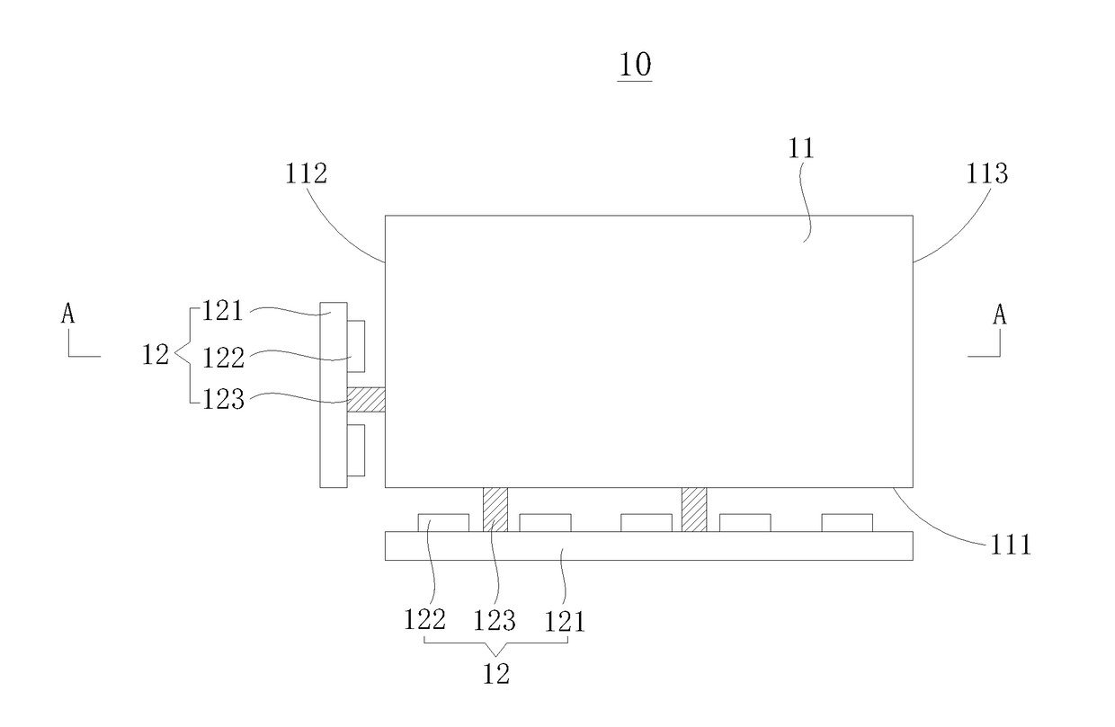
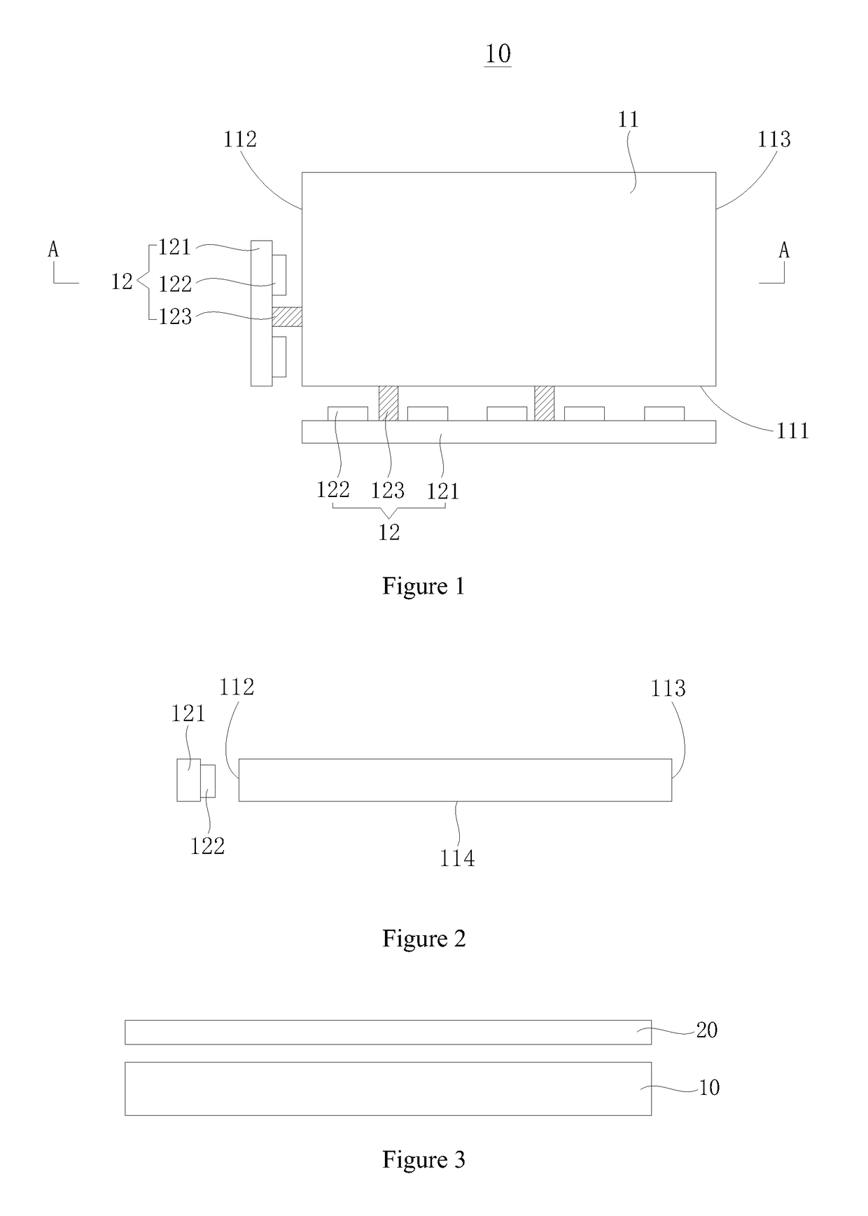
[0018]FIG. 1 is a top-view diagram showing a backlight module 10 for a liquid crystal display (LCD) device according to an embodiment of the present invention. FIG. 2 is a schematic sectional diagram showing the backlight module 10 along the A-A line of FIG. 1.

[0019]As shown in FIGS. 1 and 2, the backlight module 10 contains a light guide plate 11, and light source members 12. For people of the related art, it should be well known that the backlight module further contains other elements such as back plate, plastic frame, optical film, reflection plate, etc. As these elements are of little relevance to the present invention, their details are omitted here.

[0020]In the present embodiment, the light guide plate 11 has the shape of a cuboid. But in alternative embodiments, the light guide plate 11 can have another shape. The light guide plate 11 has a first light incident face 111, a second light incident face 112, and a third light incident face 113. The second light incident face 112...


PUM


Abstract

The backlight module contains a light guide plate and two light source members. The light guide plate has a longer light incident face and a shorter light incident face, and the longer and shorter light incident faces are end-to-end connected at a corner of the light guide plate. A first light source member is positioned oppositely along the longer light incident face, and a second light source member is positioned oppositely along the shorter light incident face. The present invention also provides a liquid crystal display (LCD) device including the backlight module. The LCD device and the backlight module achieve enhanced light coupling efficiency without interfering the thickness reduction of the LCD device and the backlight module.

Description

BACKGROUND OF THE INVENTION1. Field of the Invention[0001]The present invention relates to liquid crystal display techniques, and in particular to a liquid crystal display device and a backlight module.2. The Related Arts[0002]As large-dimensional liquid crystal displays (LCD)s with 4K or even 8K resolution become the mainstream product, the number of pixels of the LCDs increases significantly. This leads to pixels with reduced size, aperture ratio, and penetration. As such, the brightness of the backlight modules have to be increased.[0003]The conventional edge lit technique along a single longer edge of the light guide plate fails to achieve the required brightness increase, not only due to the reduced penetration but also due to the limitation from light emitting diode (LED) brightness and heat dissipation. Therefore, the existing solution is to use the edge lit technique along both the shorter or longer edges of the light guide plate. However, for a backlight module using this s...

Claims


Application Information

Patent Timeline
Patent Type & Authority Applications(United States)
IPC IPC(8): F21V8/00
CPCG02B6/0068
Inventor FAN, YONG
Owner TCL CHINA STAR OPTOELECTRONICS TECH CO LTD
Why Eureka
Try Eureka