Light Coupling Arrangement of Backlight Module

a backlight module and light coupling technology, applied in the field of backlight modules, can solve the problems of low light coupling efficiency, difficult and important light coupling distance between the lgp and the leds, and the lgp is crushed by the lgp or molten by the high temperature of the lgp, so as to simplify the assembling structure of the light guide plate, improve the light coupling efficiency of the module, and simplify the effect of the light coupling distan

Inactive Publication Date: 2014-05-01
TCL CHINA STAR OPTOELECTRONICS TECH CO LTD
View PDF12 Cites 4 Cited by
  • Summary
  • Abstract
  • Description
  • Claims
  • Application Information

AI Technical Summary

Benefits of technology

[0007]Thus, an object of the present invention is to provide a light coupling arrangement of a backlight module that simplifies a positioning structure of light guide plate and enhance the light coupling efficiency between the light guide plate and light-emitting diodes (LEDs).
[0025]The present invention provides a light coupling arrangement of a backlight module that improves the light coupling efficiency of the module and simplifies assembling structure of light guide plate. Rivet of the backplane and cutting of the light guide plate can be eliminated so as to simplify the assembling structures of the light guide plate and backplane.

Problems solved by technology

If the distance between the LGP and the LEDs is great, the problem that light coupling efficiency lowers down will occur.
If the light coupling distance is small, then the problem that the LEDs are crushed down by the LGP or molten by the high temperature of the LGP will occur.
Due to such problems, the light coupling distance between the LGP and the LEDs is a difficult and important issue for designing side-edge backlighting.
The known techniques cannot provide a promising light coupling distance between LEDs and LGP of a backlight module and this is because the light coupling distance is affected by various parameters, such as precision of diameter of the positioning pegs that mount the LGP, cutting tolerance of the LGP, tolerances of surface mounting of LED and manufacturing of printed circuit board, and thickness of heat dissipative soldering disk.
Material tolerance, assembling tolerance, and expansion will be applied to a light incidence side, leading to instability of the light coupling distance.

Method used


Image

  • Light Coupling Arrangement of Backlight Module
  • Light Coupling Arrangement of Backlight Module
  • Light Coupling Arrangement of Backlight Module

Examples


Embodiment Construction

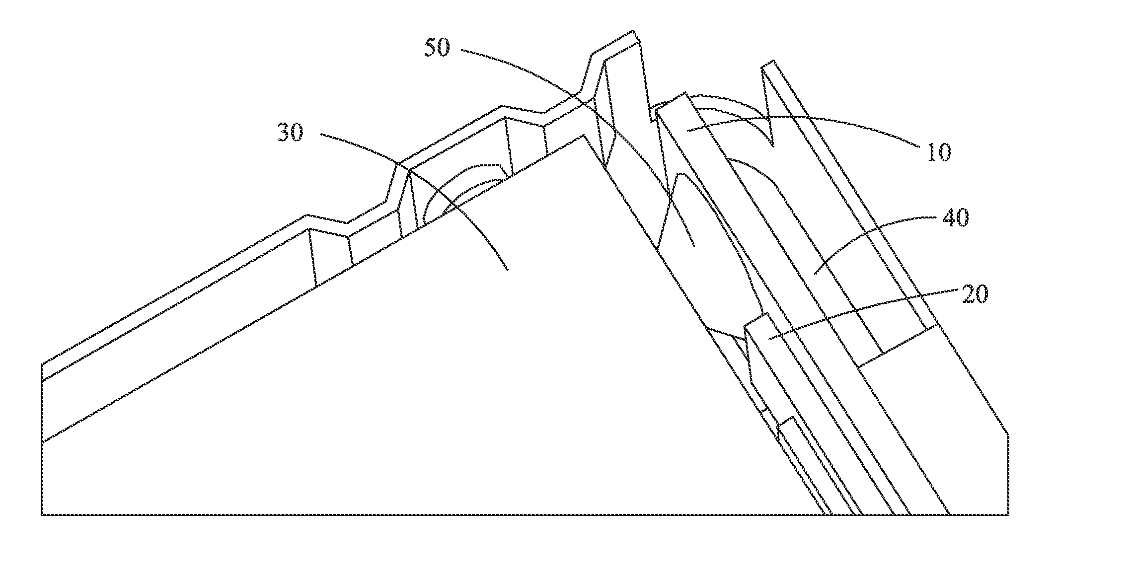
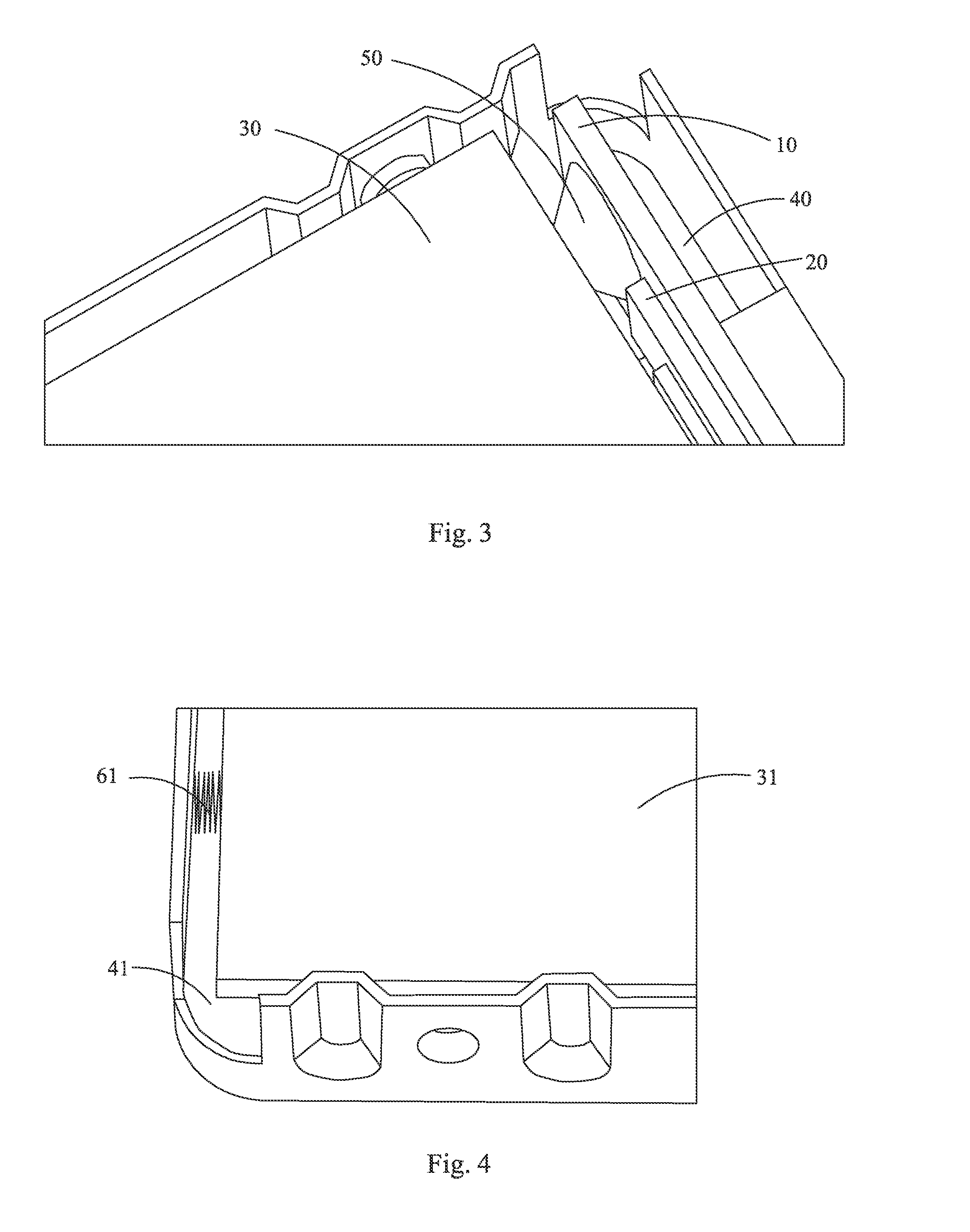
[0034]Referring to FIG. 3, which is a schematic view showing a positioning arrangement of a light incidence side of a light guide plate of the light coupling arrangement of a backlight module according to the present invention, the light coupling arrangement of a backlight module according to the present invention comprises a heat dissipation board 10, an LED light bar 20, a light guide plate 30, and a backplane 40. The heat dissipation board 10 is positioned at a light incidence side of the light guide plate 30 and is fixed to the backplane 40. The LED light bar 20 is fixed to the heat dissipation board 10 and opposes the light incidence side of the light guide plate 30. The heat dissipation board 10 forms a bump 50 that faces the light incidence side of the light guide plate 30. The bump 50 has a top that is in contact with the light incidence side of the light guide plate 30 to constrain movement of the light guide plate 30 in the light incidence direction. The light guide plate ...


PUM


Abstract

The present invention relates to a light coupling arrangement of a backlight module, which includes a heat dissipation board, an LED light bar, a light guide plate, and a backplane. The heat dissipation board is positioned at a light incidence side of the light guide plate and fixed to the backplane. The LED light bar is fixed to the heat dissipation board and opposes the light incidence side of the light guide plate. The heat dissipation board forms a bump that faces the light incidence side of the light guide plate. The bump has a top that is in contact with the light incidence side of the light guide plate to constrain movement of the light guide plate in a light incidence direction. The light guide plate has a light-opposite side, and an elastic structure is received between the light-opposite side and a side wall of the backplane.

Description

BACKGROUND OF THE INVENTION[0001]1. Field of the Invention[0002]The present invention relates to a backlight module, and in particular to a light coupling arrangement of a backlight module.[0003]2. The Related Arts[0004]A backlight module is one of the key components of a liquid crystal display device and is widely used in various electronic products, including personal digital assistant (PDA), digital camera, global positioning system, and flat panel television. With the increasing expansion of the terminal application of light-emitting diodes (LEDs), it is a definite trend that LED backlight sources will replace the cold cathode fluorescent lights. The backlight sources can be classified in two types, namely direct LED backlight module and side-edge LED backlight module, according to the location where the light source is set. The direct LED backlight module is generally constructed by uniformly distributing LED chips on a back side of a liquid crystal panel to serve as a light so...

Claims


Application Information

Patent Timeline
Patent Type & Authority Applications(United States)
IPC IPC(8): F21V8/00
CPCG02B6/0073G02B6/0085G02B6/0088G02B6/0091
Inventor ZHANG, YANXUE
Owner TCL CHINA STAR OPTOELECTRONICS TECH CO LTD
Why Eureka
Try Eureka