Optical image capturing system
- Summary
- Abstract
- Description
- Claims
- Application Information
AI Technical Summary
Benefits of technology
Problems solved by technology
Method used
Image


Examples
first embodiment
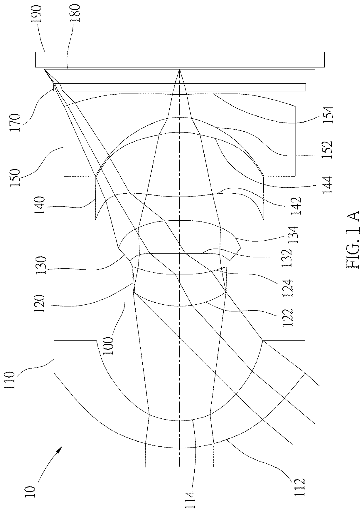
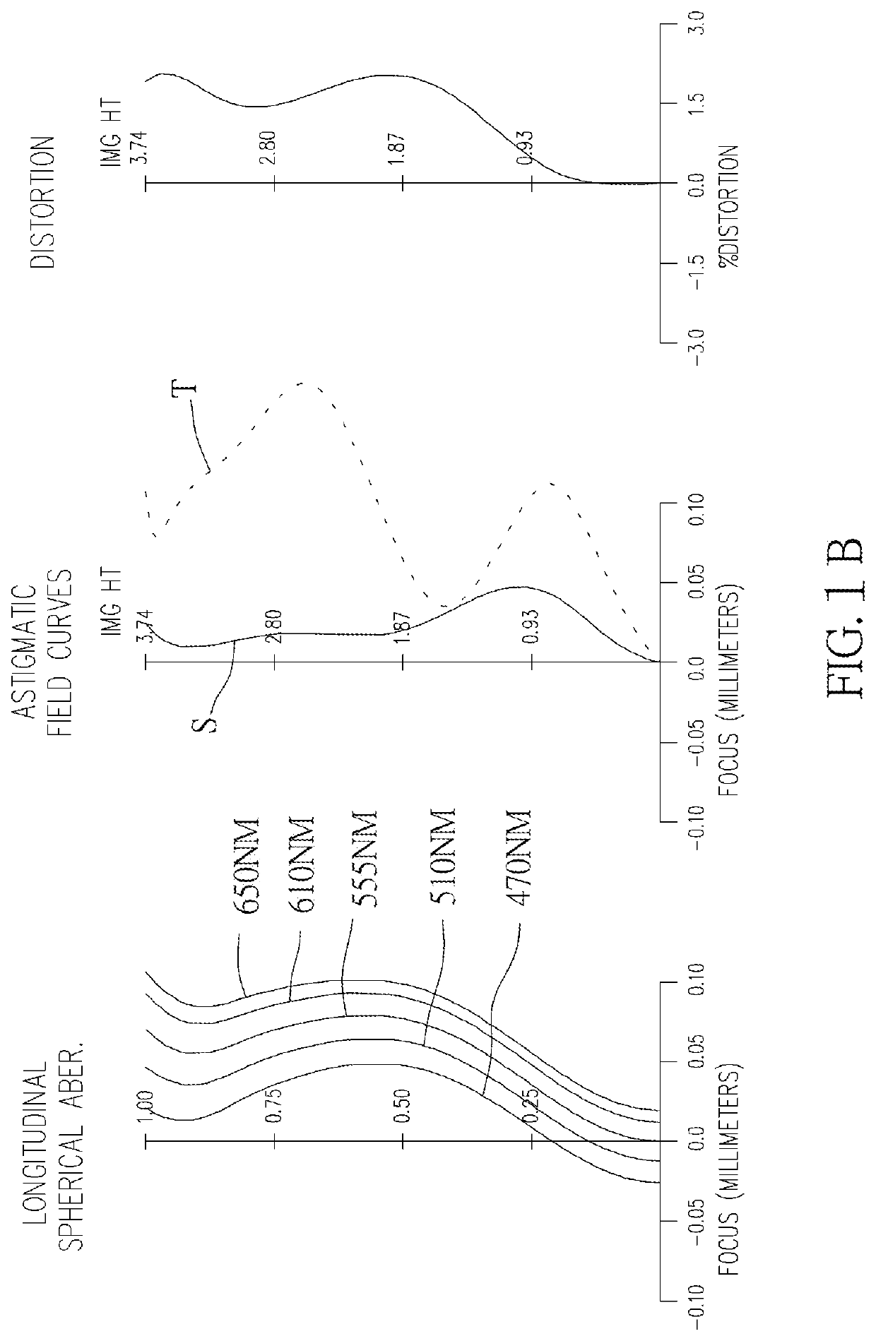
[0113]As shown in FIG. 1A and FIG. 1B, an optical image capturing system 10 of the first embodiment of the present invention includes, along an optical axis from an object side to an image side, a first lens 110, an aperture 100, a second lens 120, a third lens 130, a fourth lens 140, a fifth lens 150, an infrared rays filter 170, an image plane 180, and an image sensor 190. FIG. 1C shows a tangential fan and a sagittal fan of the optical image capturing system 10 of the first embodiment of the present application, and a transverse aberration diagram at 0.7 field of view when a longest operation wavelength and a shortest operation wavelength pass through an edge of the aperture 100. FIG. 1D is a diagram showing the through-focus MTF values of the visible light spectrum at the central field of view, 0.3 field of view, and 0.7 field of view of the first embodiment of the present invention. FIG. 1E is a diagram showing the through-focus MTF values of the infrared light spectrum at the ...
second embodiment
[0166]As shown in FIG. 2A and FIG. 2B, an optical image capturing system 20 of the second embodiment of the present invention includes, along an optical axis from an object side to an image side, a first lens 210, a second lens 220, an aperture 200, a third lens 230, a fourth lens 240, a fifth lens 250, an infrared rays filter 270, an image plane 280, and an image sensor 290. FIG. 2C shows a tangential fan and a sagittal fan of the optical image capturing system of the second embodiment of the present application, and a transverse aberration diagram at 0.7 field of view when a longest operation wavelength and a shortest operation wavelength pass through an edge of the aperture. FIG. 2D is a diagram showing the through-focus MTF values of the visible light spectrum at the central field of view, 0.3 field of view, and 0.7 field of view of the second embodiment of the present invention. FIG. 2E is a diagram showing the through-focus MTF values of the infrared light spectrum at the cent...
third embodiment
[0178]As shown in FIG. 3A and FIG. 3B, an optical image capturing system of the third embodiment of the present invention includes, along an optical axis from an object side to an image side, an aperture 300, a first lens 310, a second lens 320, a third lens 330, a fourth lens 340, a fifth lens 350, an infrared rays filter 370, an image plane 380, and an image sensor 390. FIG. 3C shows a tangential fan and a sagittal fan of the optical image capturing system of the third embodiment of the present application, and a transverse aberration diagram at 0.7 field of view when a longest operation wavelength and a shortest operation wavelength pass through an edge of the aperture. FIG. 3D is a diagram showing the through-focus MTF values of the visible light spectrum at the central field of view, 0.3 field of view, and 0.7 field of view of the third embodiment of the present invention. FIG. 3E is a diagram showing the through-focus MTF values of the infrared light spectrum at the central fi...
PUM
 Abstract
Description
Claims
Application Information
 - Generate Ideas
- Intellectual Property
- Life Sciences
- Materials
- Tech Scout
- Unparalleled Data Quality
- Higher Quality Content
- 60% Fewer Hallucinations
Browse by: Latest US Patents, China's latest patents, Technical Efficacy Thesaurus, Application Domain, Technology Topic, Popular Technical Reports.
© 2025 PatSnap. All rights reserved.Legal|Privacy policy|Modern Slavery Act Transparency Statement|Sitemap|About US| Contact US: help@patsnap.com