Electronic device and system including the same

a technology applied in the field of electronic devices and systems, can solve the problems of large amount of data and large amount of memory capacitan

Inactive Publication Date: 2019-11-07
SEMICON ENERGY LAB CO LTD
View PDF0 Cites 7 Cited by
  • Summary
  • Abstract
  • Description
  • Claims
  • Application Information

AI Technical Summary

Benefits of technology

[0013]Another object of one embodiment of the present invention is to provide a system in which a large volume of data is compressed and recorded. Another object of one embodiment of the present invention is to provide a method for compressing a large volume of data to record the data.

Problems solved by technology

In particular, when the 8K broadcast is recorded with a configuration in which image data that is decompressed (decoded) is stored in the memory device, a large volume of image data is processed, and accordingly a large amount of memory capacitance is needed.
Moreover, even in a configuration in which image data that is compressed (encoded, i.e., not decoded) is stored in the memory device, there may be a large amount of data when encoding is insufficiently performed.

Method used


Image

  • Electronic device and system including the same
  • Electronic device and system including the same
  • Electronic device and system including the same

Examples


embodiment 1

[0079]In this embodiment, a structure of an electronic device of one embodiment of the present invention and structures of an encoder and a decoder included in the electronic device will be described.

[0080]

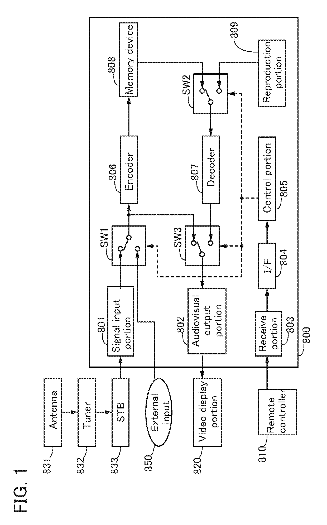
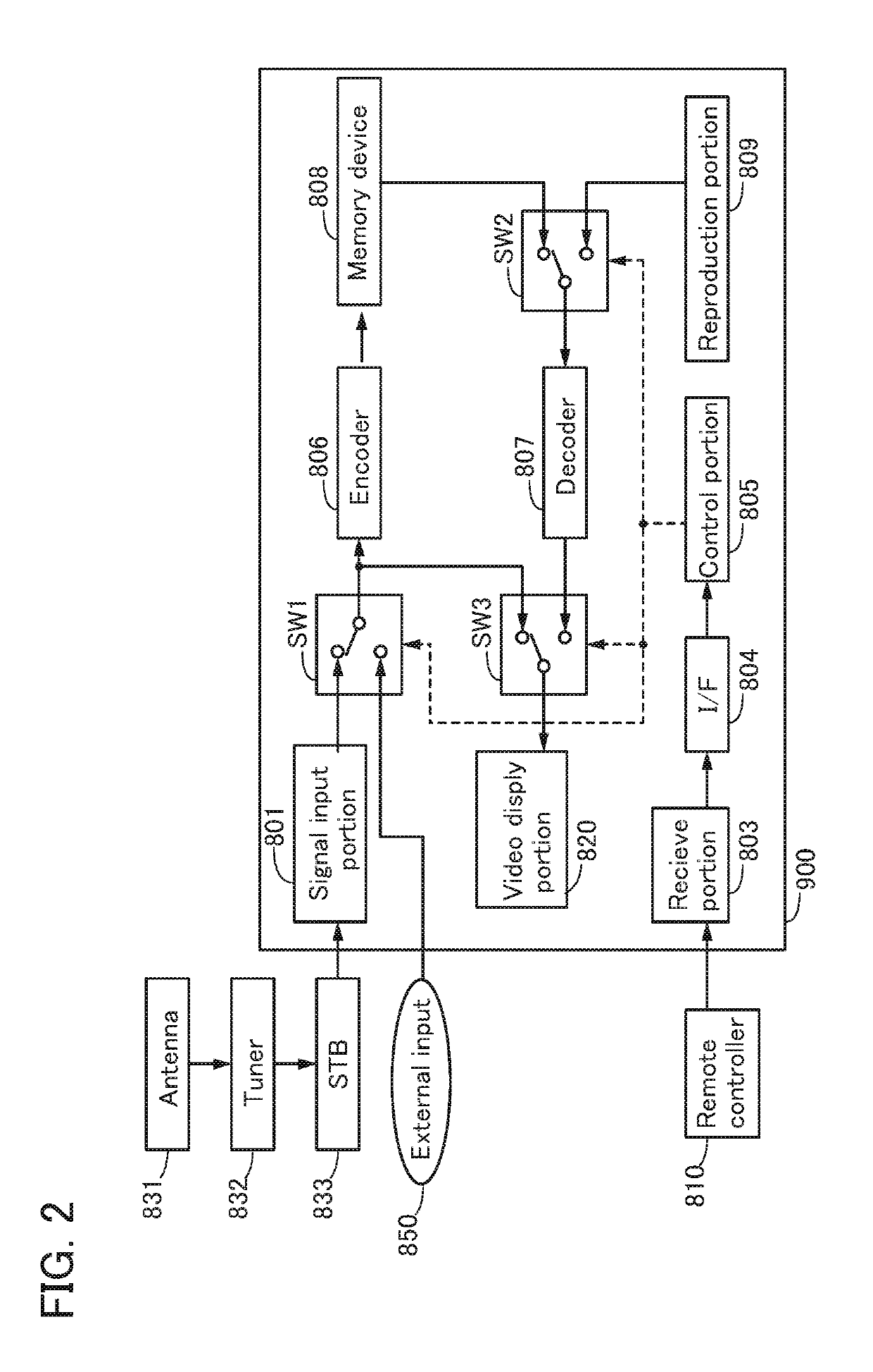
[0081]FIG. 1 shows a configuration example of an electronic device capable of recording 8K broadcast and its peripheral devices. An electronic device 800 includes a signal input portion 801, an audiovisual output portion 802, a receive portion 803, an interface (I / F) 804, a control portion 805, an encoder 806, a decoder 807, a memory device 808, a reproduction portion 809, and switches SW1 to SW3. Furthermore, this configuration example includes a remote controller 810, a video display portion 820, an antenna 831, a tuner 832, and a set top box (STB) 833 as peripheral devices of the electronic device 800.

[0082]The antenna 831 is electrically connected to the signal input portion 801 in the electronic device 800 via the tuner 832 and the STB 833. The video display portion 820 is el...

embodiment 2

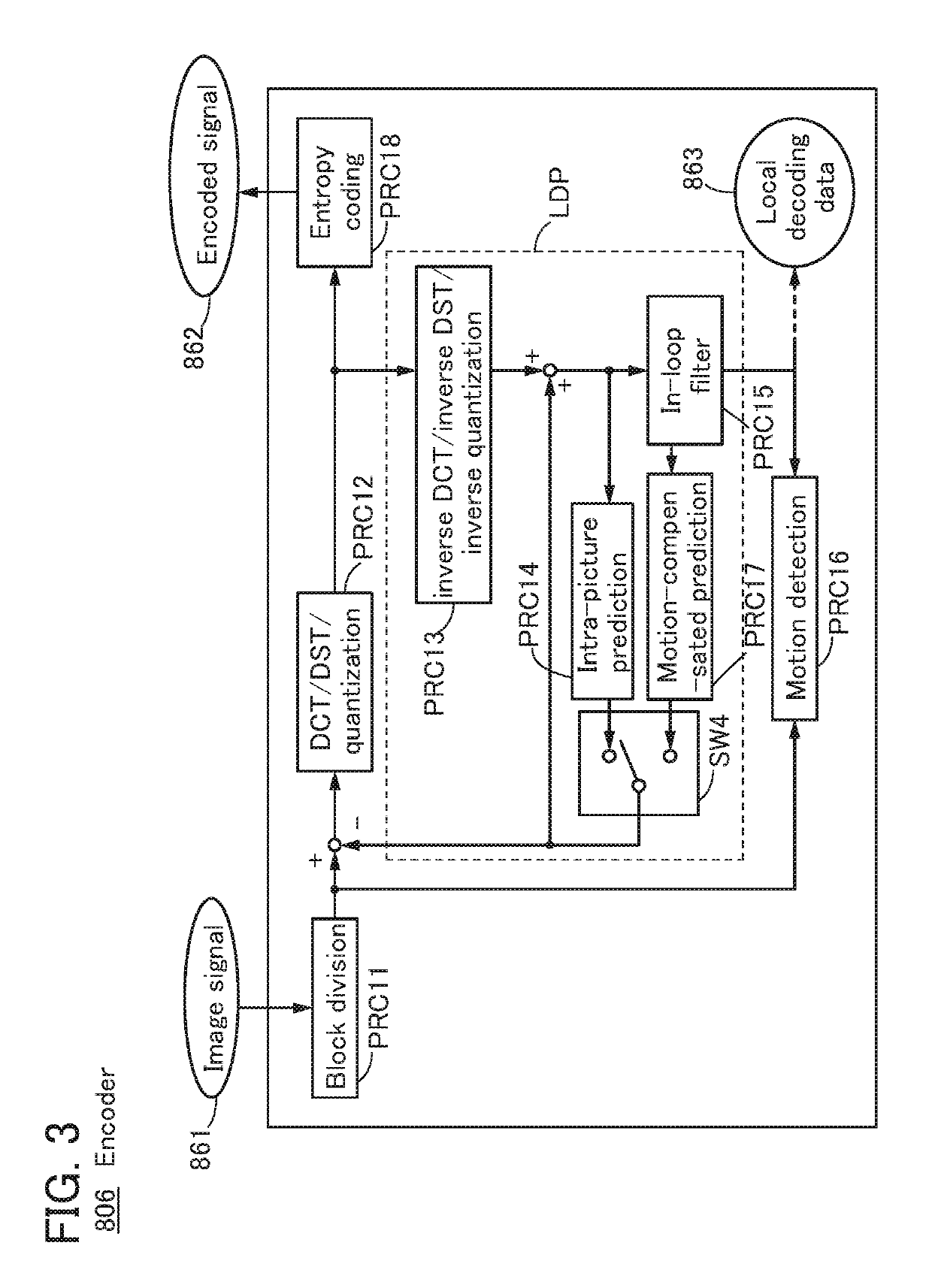
[0137]In this embodiment, a configuration of circuit (semiconductor device) for performing the motion detection PRC 16 and the motion-compensated prediction PRC 17 by the encoder described in Embodiment 1 will be described.

[0138]

[0139]First, an example of a method for detecting a motion of an object included in a displayed image will be described with reference to FIGS. 5A to 5F.

[0140]FIGS. 5A to 5F illustrate an algorithm for detecting an object motion in image data.

[0141]FIG. 5A shows image data 10 that has a triangle 11 and a circular 12. FIG. 5B shows image data 20 where the triangle 11 and the circle 12 of the image data 10 are moved to the upper right.

[0142]Image data 30 in FIG. 5C shows operation by which a region 31 including the triangle 11 and the circle 12 is extracted from the image data 10. In the image data 30, a cell at the upper left corner of the extracted region 31 is regarded as a reference point (0, 0), and numbers indicating positions in the right / left direction...

embodiment 3

[0433]In this embodiment, a connection structure of the electronic device and its peripheral devices, which are described in Embodiment 1, will be described.

[0434]FIGS. 24A to 24C each illustrate a connection structure of the electronic device 800 illustrate in FIG. 1, an electronic device provided with a video display portion, a receiver, and antennas. In particular, FIGS. 24A to 24C each illustrate an example of a mode of the receiver. Note that the receiver in this embodiment includes the tuner 832 and the STB 833 described in Embodiment 1.

[0435]FIG. 24A illustrates a connection structure of an electronic device 899 including the video display portion 820, the electronic device 800, a receiver 871, an antenna 1564, and an antenna 1565. The antenna 1564 and the antenna 1565 are electrically connected to the receiver 871. The receiver 871 is electrically connected to the electronic device 800, and the electronic device 800 is electrically connected to the video display portion 820....


PUM


Abstract

An electronic device that efficiently compresses a large volume of data included in a broadcast signal and stores the compressed data is to be provided. The broadcast signal is decoded and decompressed through a tuner and a set top box (STB), and a signal (image data) that is decoded and decompressed is inputted to a video display device, so that an image based on the signal is displayed. As a unit for efficiently compressing and storing the image, an electronic device including an encoder, a decoder, and a memory device is used. An image data outputted from the tuner and the STB is compressed using the encoder, and the compressed data is stored in the memory device. To reproduce and display the image data. the compressed image data is decompressed by the decoder, and the decompressed image data is inputted to the video display device. For the compression of the image data in the encoder, an analog processing circuit included in the encoder or a semiconductor device in which a neural network is constructed is used.

Description

TECHNICAL FIELD[0001]One embodiment of the present invention relates to an electronic device and a system including the electronic device.[0002]Note that one embodiment of the present invention is not limited to the above technical field. The technical field of the invention disclosed in this specification and the like relates to an object, a method, or a manufacturing method. In addition, one embodiment of the present invention relates to a process, a machine, manufacture, or a composition of matter. Specifically, examples of the technical field of one embodiment of the present invention disclosed in this specification include a semiconductor device, a display device, a liquid crystal display device, a light-emitting device, a power storage device, an imaging device, a memory device, a processor, a converter, an encoder, a decoder, a tuner, an electronic device, a method for driving any of them, a method for manufacturing any of them, a method for testing any of them, and a system ...

Claims


Application Information

Patent Timeline
Patent Type & Authority Applications(United States)
IPC IPC(8): H04N21/438H04N19/172H04N19/423H04N19/52
CPCH04N19/423H04N21/4382H04N19/52H04N19/172H04N9/8042H04N19/51H04N19/61H04N19/43H04N5/775G06N3/049G06N3/08G06N3/065G06N3/044
Inventor KUROKAWA, YOSHIYUKI
Owner SEMICON ENERGY LAB CO LTD
Why Eureka
Try Eureka