
Footwear construction

Active Publication Date: 2019-11-14
WOLVERINE OUTDOORS
View PDF0 Cites 15 Cited by
  • Summary
  • Abstract
  • Description
  • Claims
  • Application Information

AI Technical Summary

Benefits of technology

The patent describes a shoe design that includes multiple compression units. These units are placed in the midsole and adjacent to the outsole, which helps to efficiently distribute forces and assist in correct foot motion during gait. By linking together the compression units, they help to provide a more stable foot support and resist torsional movement. Additionally, the compression units can be specifically placed under certain bones of the foot to impact attenuate and provide energy return during different stages of gait. Overall, this design provides better impact protection, improved foot motion, and higher energy return compared to previous shoe designs.

Problems solved by technology

A highly cushioned sole, designed to compress and efficiently absorb significant impact forces, may not provide sufficient foot support, and this may lead to premature foot fatigue.
Such a cushioned sole also might not allow a proper distribution of forces along the bottom of the foot during a gait cycle, which can lead to an erratic torsional, lateral, or lengthwise twisting or rotation of the foot, which can be deleterious to the gait of the wearer.
On the other hand, an overly firm sole, designed to provide support and stabilize the foot during the gait cycle, may feel uncomfortable, and may not provide the cushioning needed to protect the wearer against potential damage or injury associated with repeated ground impact.
Furthermore, such a sole might be so rigid that it impairs the foot from following its natural flexing and bending form through the gait cycle, which can also alter the wearer's gait in such a way so as to reduce efficiency and energy return.

Method used


Image

  • Footwear construction
  • Footwear construction
  • Footwear construction

Examples


Embodiment Construction

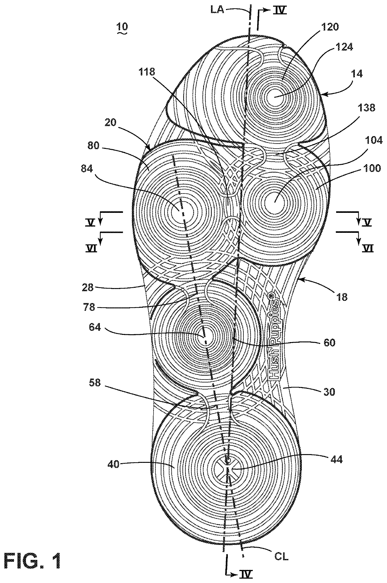
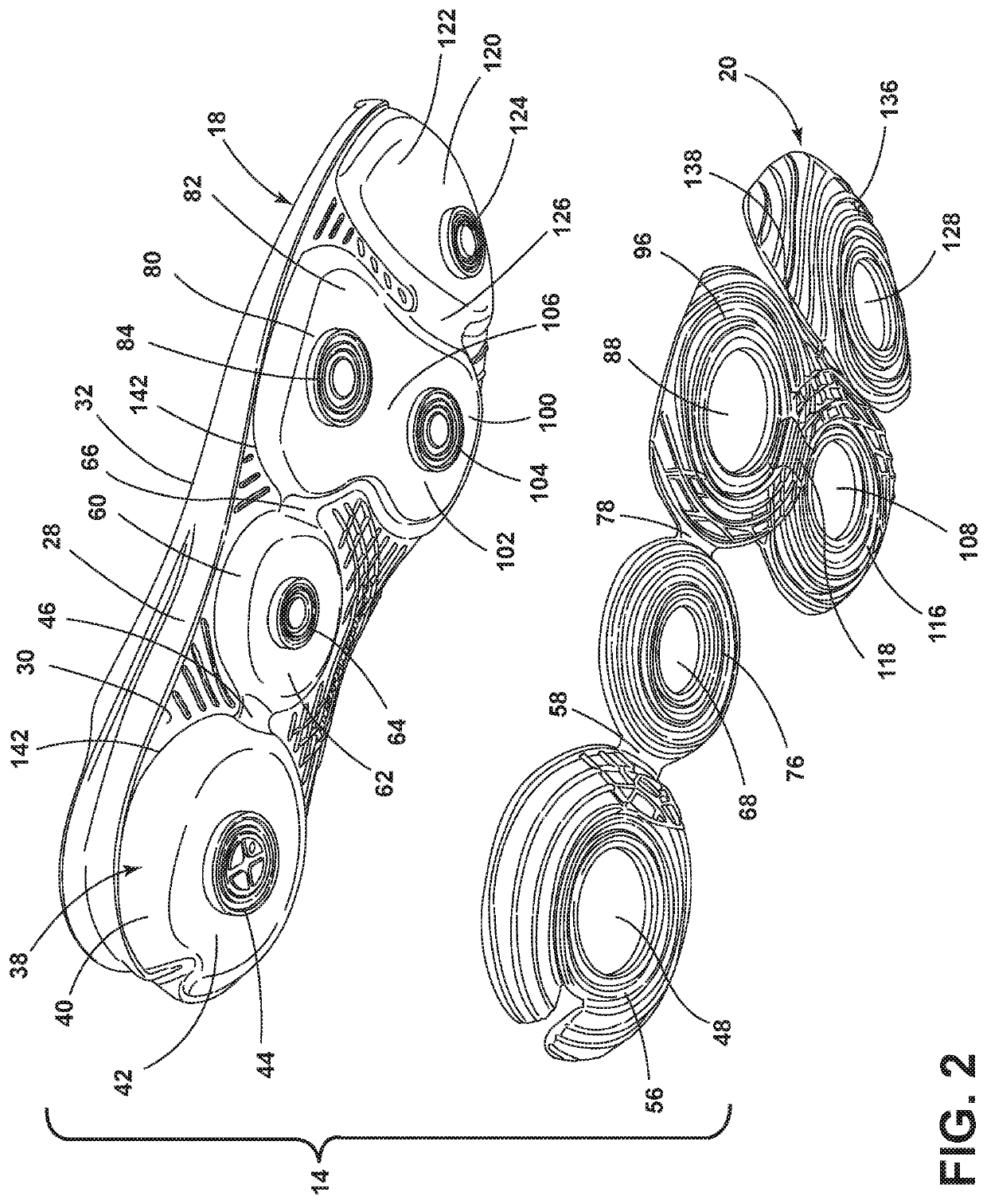
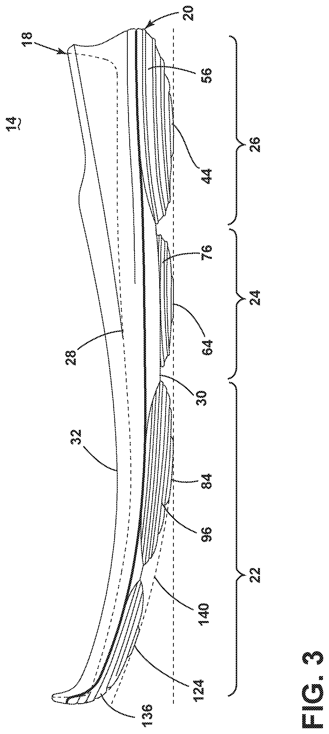
[0026]A current embodiment of the footwear is illustrated in FIGS. 1-7, and generally designated 10. In these embodiments, the improved article of footwear includes a sole assembly configured to provide benefits in impact attenuation, foot motion, and energy return.

[0027]Although the current embodiment of footwear is illustrated in the context of a performance shoe, it may be incorporated into any type or style of footwear, including casual shoes, trail shoes and boots, hiking shoes, work boots, all-terrain shoes, barefoot running shoes, athletic shoes, running shoes, sneakers, conventional tennis shoes, walking shoes, multisport footwear, boots, dress shoes or any other type of footwear or footwear components. It also should be noted that directional terms, such as “vertical,”“horizontal,”“top,”“bottom,”“upper,”“lower,”“inner,”“inwardly,”“outer”, “outwardly,”“below” and “above” are used to assist in describing the embodiments based on the orientation of the embodiments shown in the...


PUM


Abstract

A sole assembly is provided including multiple compression units entrapped in a midsole and adjacent an outsole to efficiently distribute forces and to assist in correct foot motion during a gait cycle. The multiple compression units can be linked to one another to assist the foot in moving through an appropriate foot motion during a gait cycle. A heel compression unit can be linked to an arch compression unit, which can be linked to one or more forefoot compression units, which can be linked to a toe compression unit. The linking of the heel compression unit, the arch compression unit, and the forefoot compression unit to one another can resist torsional movement of the units between one another, thereby providing a more stable foot support, while still providing impact-attenuation and force distribution through the sole assembly.

Description

BACKGROUND OF THE INVENTION[0001]The present invention relates to footwear, and more particularly to a sole assembly for footwear.[0002]There are a variety of footwear constructed for efficient function in different activities. Many footwear are designed to provide a high level of stable support, coupled with impact attenuation upon engagement with an underfoot surface, such as the ground. Much of the support and impact protection afforded by footwear is attributable to the configuration of the sole. The sole protects the foot by dispersing significant forces caused by running, jumping, training and even walking. The sole also provides cushioning that absorbs impact and protects the wearer's appendages, such as their feet, ankles and knees, from the stress associated with strenuous and even day-to-day activities. At the same time, the sole plays a role in helping support the foot in its proper shape to prevent a wearer's feet and legs from becoming fatigued over time.[0003]The objec...

Claims


Application Information

Patent Timeline
IPC IPC(8): A43B13/18A43B7/14A43B3/00A43B7/32A43B13/14A43B13/16
CPCA43B13/16A43B13/186A43B7/142A43B7/32A43B3/0042A43B7/145A43B13/184A43B13/141A43B7/144A43B13/125
Inventor DEAN, MARTIN W.F.
Owner WOLVERINE OUTDOORS
Learn More