Vehicle display device

a display device and vehicle technology, applied in vehicle components, mountings, instruments, etc., can solve the problems of difficult to suppress the temperature rise of the display at an appropriate timing, the display may overheat, and the irradiation of external light to the display is difficult to be accurately detected, so as to prevent damage to the display and accurately detect external light

Active Publication Date: 2019-11-14
YAZAKI CORP
View PDF5 Cites 14 Cited by
  • Summary
  • Abstract
  • Description
  • Claims
  • Application Information

AI Technical Summary

Benefits of technology

[0006]The present invention is made in view of the above problems, and an object thereof is to provide a vehicle display device that accurately detects external light with which a display is irradiated via a reflective mirror and prevent damage of a display due to external light.
[0009]According to still another aspect of the present invention, the vehicle display device may further include a temperature sensor that detects a temperature of the display, wherein the controller may restrict execution of the temperature decreasing operation when the optical sensor detects the external light and a detected value by the temperature sensor is equal to or less than a threshold value.
[0010]According to still another aspect of the present invention, the vehicle display device may further include a temperature sensor that is disposed at least in a vehicle and outside the vehicle display device, wherein the controller may restrict execution of the temperature decreasing operation when the optical sensor detects the external light and a detected value by the temperature sensor is equal to or less than a threshold value.

Problems solved by technology

For example, when external light such as sunlight enters from the opening and reaches the display via, for example, a reflective mirror, the display may overheat due to a light condensing action of the reflective mirror, for example.
However, since dimming of the display, for example, is executed after the temperature of the display exceeds a threshold temperature, it is difficult to suppress a temperature rise of the display at an appropriate timing.
Therefore, irradiation of external light to a display is difficult to be accurately detected, which leaves room for improvement.

Method used


Image

  • Vehicle display device
  • Vehicle display device
  • Vehicle display device

Examples


first embodiment

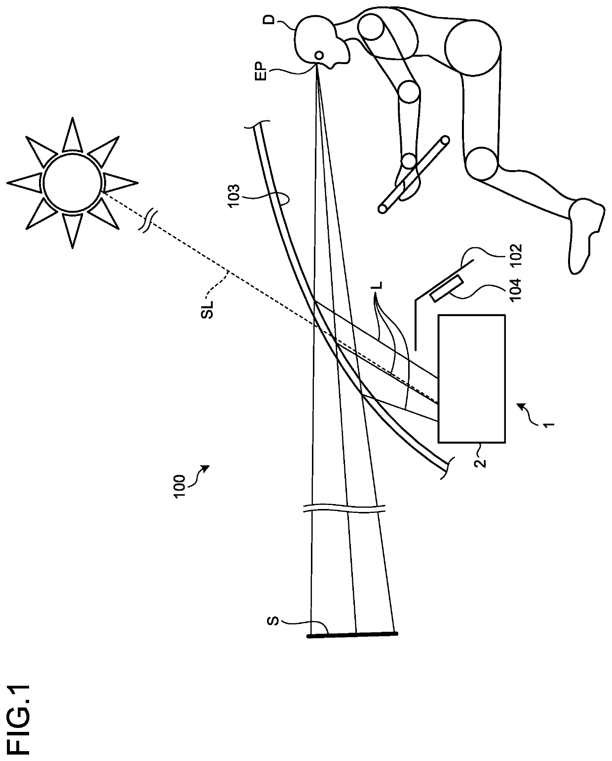
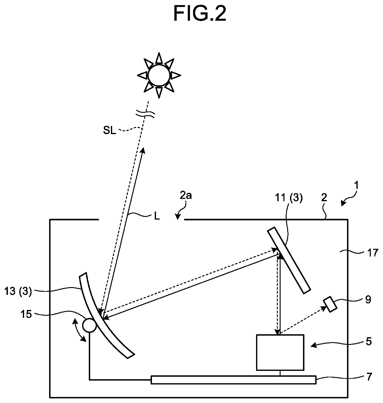
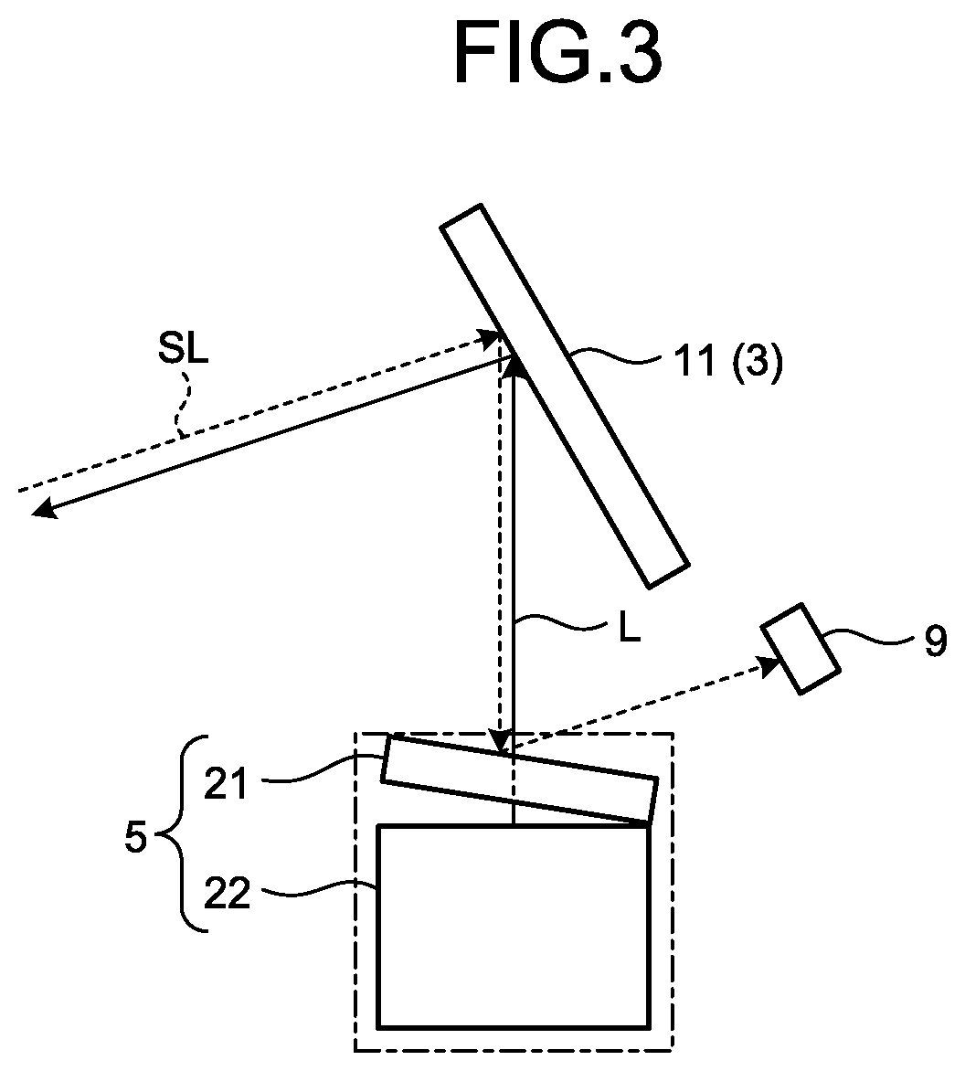
[0023]FIG. 1 is a schematic view illustrating a schematic configuration of a vehicle mounted with a vehicle display device according to a first embodiment. FIG. 2 is a schematic view illustrating a schematic configuration of the vehicle display device according to the first embodiment. FIG. 3 is a schematic view illustrating a schematic configuration of a display according to the first embodiment.

[0024]A vehicle display device 1 is, as illustrated in FIG. 1, a head up display device mounted in a vehicle 100 such as an automobile, for example. In the vehicle 100, the vehicle display device 1 is disposed inside an instrument panel 102 together with a meter 104 and projects a display image on a windshield 103. The vehicle display device 1 projects a display image on the windshield 103, as a projection target, and displays a virtual image S in front of an eye point EP of a driver D. With a semi-transmissive property that reflects a part of entering light and transmits the other part, th...

second embodiment

[0042]Next, a vehicle display device according to a second embodiment will be described with reference to FIGS. 5 to 7. FIG. 5 is a schematic view illustrating a schematic configuration of the vehicle display device according to the second embodiment. FIG. 6 is a schematic view illustrating a schematic configuration of a display according to the second embodiment. FIG. 7 is a flowchart illustrating an example of control operation of a controller according to the second embodiment.

[0043]A vehicle display device 1B according to the second embodiment differs from the vehicle display device 1 according to the first embodiment in that a temperature sensor 29 is provided inside the display 5 as illustrated in FIGS. 5 and 6. In the following description, components common to those in the first embodiment bear identical signs, and description thereof is omitted or simplified.

[0044]The temperature sensor 29 detects the temperature of the display 5 and includes, for example, a thermistor, a t...


PUM

PropertyMeasurementUnit
temperatureaaaaaaaaaa
thresholdaaaaaaaaaa
threshold temperatureaaaaaaaaaa

Abstract

A vehicle display device includes a display that emits a display image projected on a windshield provided outside as display light, two reflective mirrors that are disposed on a light path of the display light from the display to the windshield and reflect the display light, an optical sensor that detects the external light entering from an opening communicating between the outside and an internal space, and a controller configured to execute temperature decreasing operation of the display for decreasing a temperature thereof when the optical sensor detects the external light. The optical sensor is disposed at a position to which external light directed toward the display via the reflective mirror is reflected by the display to be directed.

Description

CROSS-REFERENCE TO RELATED APPLICATION(S)[0001]The present application claims priority to and incorporates by reference the entire contents of Japanese Patent Application No. 2018-091933 filed in Japan on May 11, 2018, Japanese Patent Application No. 2018-199387 filed in Japan on Oct. 23, 2018 and Japanese Patent Application No. 2019-039855 filed in Japan on Mar. 5, 2019.BACKGROUND OF THE INVENTION1. Field of the Invention[0002]The present invention relates to a vehicle display device.2. Description of the Related Art[0003]Conventionally, some vehicles such as automobiles are mounted with a head up display (HUD) device. A head up display device causes a driver to visually recognize a display image displayed on a display as a virtual image by projecting the display image on a windshield or a combiner via a reflective mirror, for example. In a head up display device, when a display image displayed on a display in a housing is projected on, for example, a windshield outside a housing, ...

Claims


Application Information

Patent Timeline
Patent Type & Authority Applications(United States)
IPC IPC(8): G02F1/1333G02B27/01
CPCG02B27/0101G02B27/0149G02F1/133382G02F1/133605B60K35/00B60K2370/1529B60K2370/334G09G3/3406G02B7/008G03B21/16G09G2330/045
Inventor MIYAKE, YUTAYAGI, KENJIMURATA, NAOHISAMUKOJIMA, HIDETOSHI
Owner YAZAKI CORP
Why Eureka
Try Eureka