Method and system for detecting an elevated object situated within a parking facility

Active Publication Date: 2019-11-21
ROBERT BOSCH GMBH
View PDF37 Cites 2 Cited by
  • Summary
  • Abstract
  • Description
  • Claims
  • Application Information

AI Technical Summary

Benefits of technology

[0003]An object of the present invention is to provide for efficiently detecting an elevated object situated wi

Problems solved by technology

However, if an elevated object is situated on a visual axis between the overlap area and one of the video cameras, this one video camera does not have the same view as the other video cameras.
Otherwise, it might be necessary to wait for the result of the video camera, which is time-consuming.
In contrast, video cameras of

Method used


Image

  • Method and system for detecting an elevated object situated within a parking facility
  • Method and system for detecting an elevated object situated within a parking facility
  • Method and system for detecting an elevated object situated within a parking facility

Examples


Example

[0162]The same reference numerals may be used for identical features in the following description.

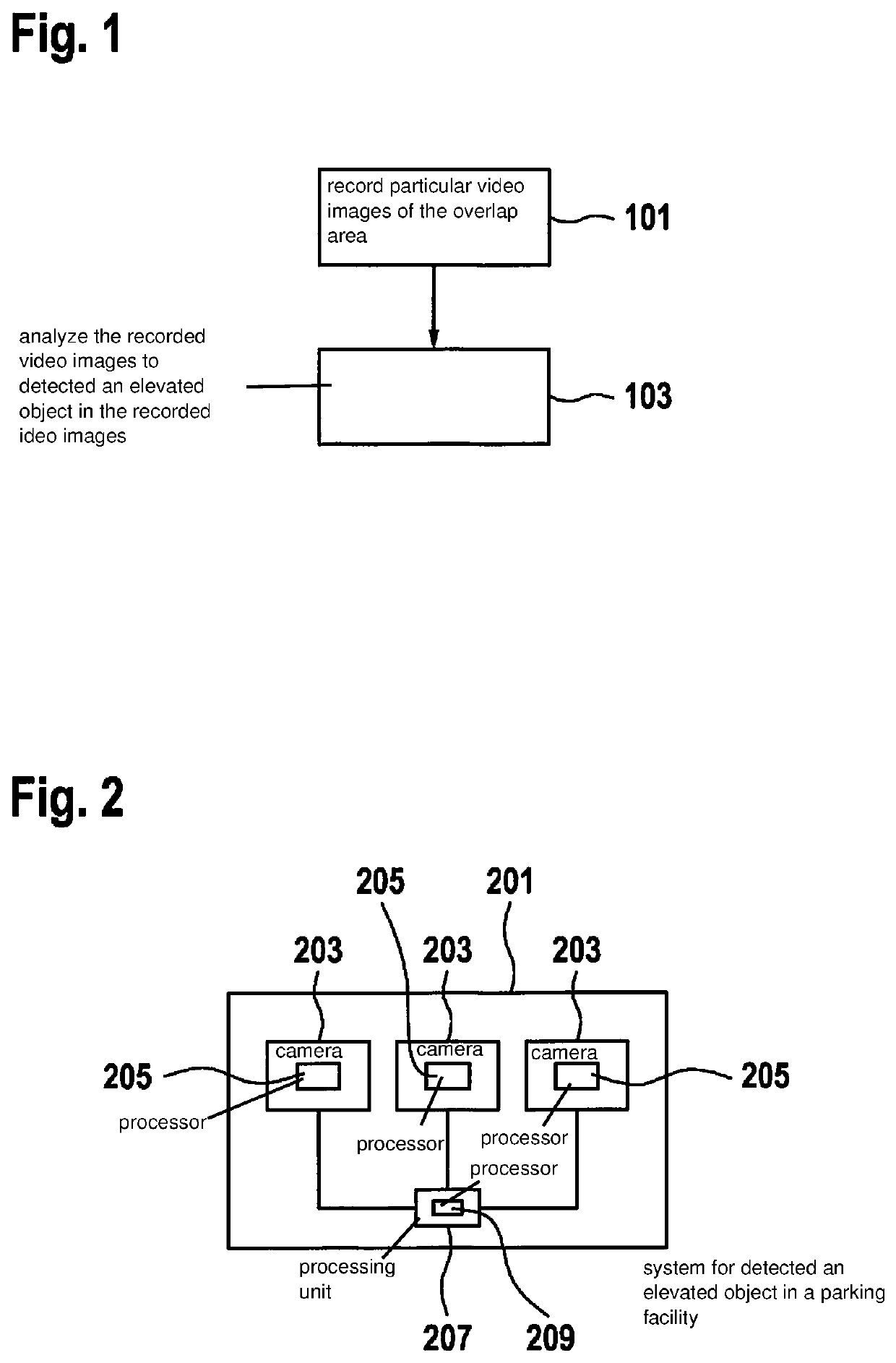
[0163]FIG. 1 shows a flow chart of a method for detecting an elevated object situated within a parking facility, using at least two video cameras that are spatially distributed within the parking facility, and whose visual ranges overlap in an overlap area.

[0164]The method encompasses the following steps:[0165]recording 101 particular video images of the overlap area with the aid of the video cameras,[0166]analyzing 103 the recorded video images in order to detect an elevated object in the recorded video images,[0167]analysis 103 being carried out internal to the video camera with the aid of at least one of the video cameras, and also external to the video camera with the aid of at least one processing unit that is different from the video cameras.

[0168]A detected elevated object may be classified as follows, for example: motor vehicle, pedestrian, cyclist, animal, baby stroller, other....


PUM


Abstract

A method for detecting an elevated object situated within a parking facility, using at least two video cameras that are spatially distributed within the parking facility and whose visual ranges overlap in an overlap area. The method encompasses the following steps: recording particular video images of the overlap area with the aid of the video cameras; analyzing the recorded video images in order to detect an elevated object in the recorded video images, the analysis being carried out internal to the video camera with the aid of at least one of the video cameras, and also external to the video camera with the aid of at least one processing unit that is different from the video cameras. Moreover, a corresponding system, a parking facility, and a computer program, are provided.

Description

FIELD[0001]The present invention relates to a method for detecting an elevated object situated within a parking facility, for example a parking deck, in particular within a driving path of a parking facility. Moreover, the present invention relates to a system for detecting an elevated object situated within a parking facility, for example a parking deck, in particular within a driving path of a parking facility. Moreover, the present invention relates to a parking facility. Furthermore, the present invention relates to a computer program.BACKGROUND INFORMATION[0002]German Patent Application No. DE 10 2015 201 209 A1 describes a valet parking system for automatically bringing a vehicle from a handover zone to an assigned parking space within a predefined parking area. The conventional system encompasses a parking facility monitoring system with at least one stationary sensor unit. The parking facility monitoring system is designed to locate the vehicles traveling within the predefin...

Claims


Application Information

Patent Timeline
IPC IPC(8): G06K9/00H04N5/225H04N5/247H04N7/18G08G1/04
CPCH04N7/181G06K9/00771H04N5/247H04N5/2253G08G1/04G06K9/00758G08G1/096725G08G1/096758G08G1/096775G06V20/586G06V20/48G06V20/52H04N23/54H04N23/90
Inventor LEHN, ANDREASHESS, FELIXNORDBRUCH, STEFAN
Owner ROBERT BOSCH GMBH
Why Eureka
Try Eureka