Throwable Objects

a technology of throwing objects and objects, which is applied can solve the problems of polluting the true distance measurement data, the accelerometer is not able to distinguish between motions of balls in the hand, and the flight information of electronic balls is limited in the field of throwing objects, so as to improve the accuracy of height measurement, and improve the effect of determination or distinction

Inactive Publication Date: 2019-11-28
TOMTOM INT BV
View PDF0 Cites 0 Cited by
  • Summary
  • Abstract
  • Description
  • Claims
  • Application Information

AI Technical Summary

Benefits of technology

[0013]The barometric pressure sensor may be any electronic device that can measure atmospheric pressure. Such sensors are also known as pressure altimeters or altitude meters. In a preferred set of embodiments the barometric pressure sensor is arranged to measure the height of the object based on an atmospheric pressure measurement. Typically, such a sensor may allow for height measurements with an accuracy of ±10 cm. The Applicant has realised that a barometric pressure sensor provides benefits over an IMU for height measurement, because it can measure the height of the object relative to the ground during a throw. This avoids the need for manual input of a starting height for the object before the throw. It is also made easier for the processor to calculate a cumulative height for multiple throws. Preferably the barometric pressure sensor further comprises a temperature sensor, and is arranged to measure the height of the object based on an atmospheric pressure and temperature measurement. This improves the accuracy of the height measurement.
[0014]The throwable object may comprise one or more further sensors to assist in measuring travel data of interest. In a preferred set of embodiments the body further houses a capacitive proximity sensor arranged to measure a change in capacitance at the surface of the body. The Applicant has recognised that such a capacitive proximity sensor can provide measurements that advantageously enable the processor to detect the difference between the object being caught and hitting the ground (not caught). Such detection may be improved if the object is provided with a clearance between the capacitive proximity sensor and the location where the hands may hold the object, such as a non-metallic, or more generally, a non-conducting shell. A measurement of deceleration from the IMU does not distinguish between the different ways that the object reaches the end of a throw, i.e. caught or not caught. In a preferred set of embodiments the processor is arranged to determine that the object is in touch-contact, or has been thrown, based on the measured change in capacitance. In various embodiments the processor, optionally by using the travel data, may be arranged to determine that or distinguish whether the object is in-flight, is being thrown, is being caught, is hitting the ground, is being hand-held or has been resting on the ground. Such determination or distinction may be improved if the object is provided with a clearance between the capacitive proximity sensor and the location where the hands may hold the object, such as a non-metallic, or more generally, a non-conducting shell.

Problems solved by technology

However existing electronic balls are limited in terms of the flight information they can accurately generate in relation to the distance, height and speed that the ball is thrown.
For example, an accelerometer is not able to distinguish between motion of a ball in the hand and motion of a ball through the air.
When a swing is given to a ball by a player before it is thrown, the accelerometer will generate travel information assuming that it is already in mid-air, which pollutes the true distance measurement data.

Method used


Image

  • Throwable Objects
  • Throwable Objects
  • Throwable Objects

Examples


Embodiment Construction

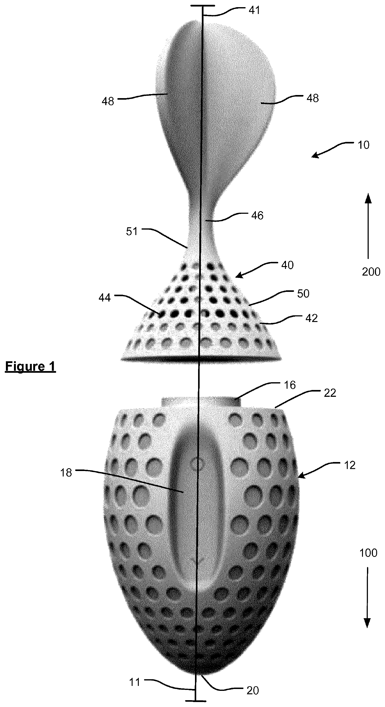
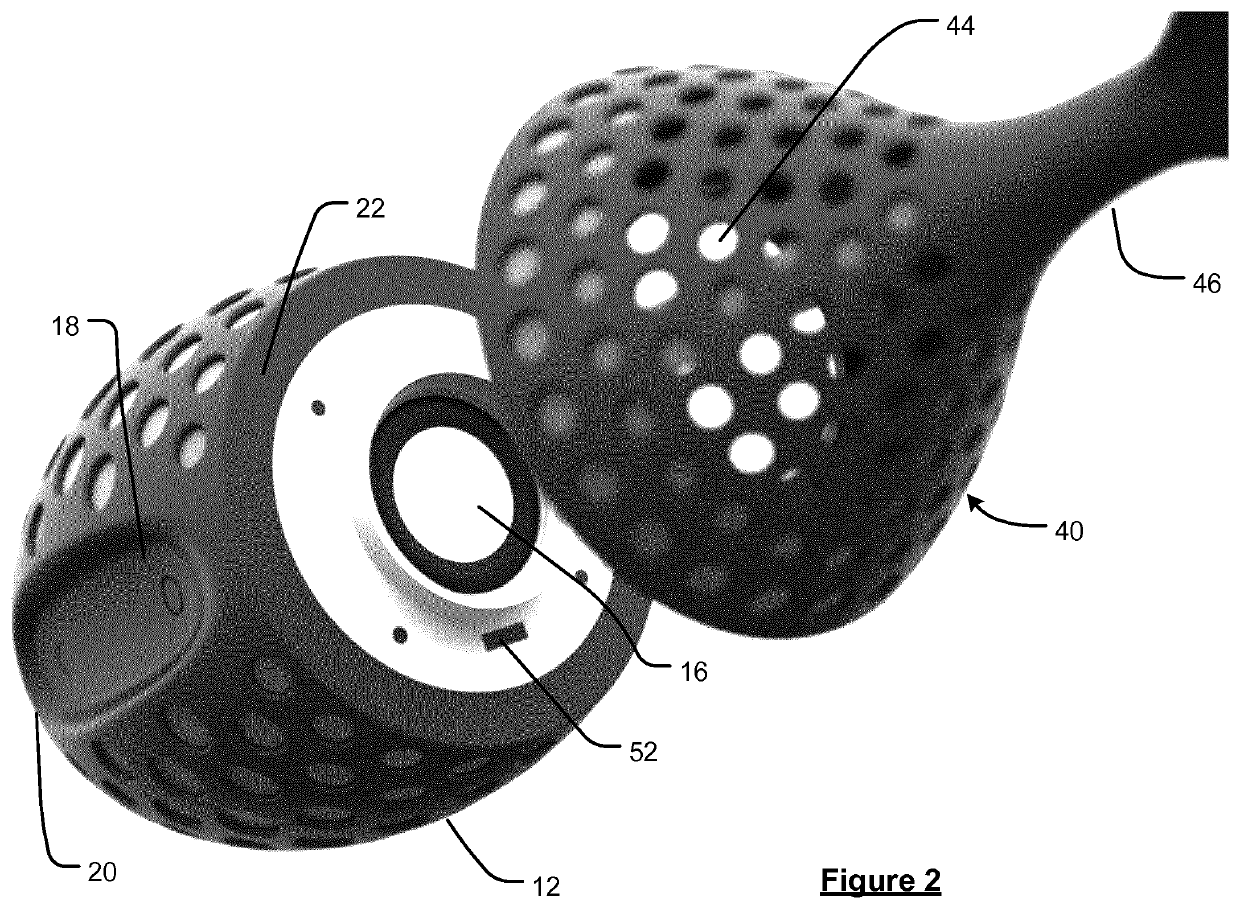
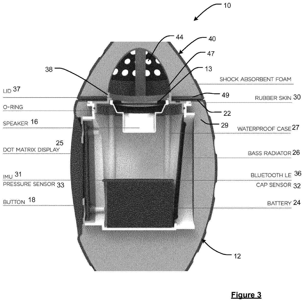
[0057]FIGS. 1 to 3 show a shuttle 10 which a user may pick up and throw. The shuttle 10 has a head 12 that is removably connected to a tail 40. The connection is such that the major axis 11 of the head 12 is collinear with the major axis of the tail 40.

[0058]The head 12 has a front end 20 and a back end 22. The front end 20 is shaped to provide the least amount of drag against the forward movement of the shuttle 10 when the front end 20 faces the forward direction 100. The back end 22 is substantially planer in a plane that is orthogonal to the major axis 11 of the head 12.

[0059]The head also comprises: a speaker 16, a speaker cavity 27, a bass radiator 26, an electronic circuit board 23, a battery 24, a power button 18 for turning the electronics on / off, a dot matrix display 25, a push-fit fastener 37, and a charging port for (re)charging the battery 24.

[0060]The push-fit fastener 37 defines a circular lip 38 surrounding a circular aperture 13 at the back end 22. The circular apert...


PUM


Abstract

Embodiments of the invention relate to throwable toys such as shuttles and balls. In some of the illustrative embodiments a shuttle includes means to determine information relating to the throw or state of motion of the shuttle, and means to convey an audio information signal to a user during the throw.

Description

FIELD OF THE INVENTION[0001]This invention relates to throwable objects. Illustrative embodiments of the invention relate to throwable toys such as shuttles and balls. In some illustrative embodiments a shuttle includes means to determine information relating to the throw or state of motion of the shuttle, and means to convey an audio information signal to a user during the throw.BACKGROUND OF THE INVENTION[0002]It is known to play a variety of games using throwable objects such as shuttles, football and vortex footballs. More recently, such throwable objects have incorporated on-board electronics to measure and display information such as the distance travelled by the ball, for example using an accelerometer in combination with a microprocessor as disclosed by U.S. Pat. No. 5,779,576. US 2008 / 0234077 discloses a ball comprising a motion switch that emits a sound at different intervals when passed from player to player to indicate to the players a stage of the game, e.g. when playin...

Claims


Application Information

Patent Timeline
Patent Type & Authority Applications(United States)
IPC IPC(8): A63B71/06A63B24/00A63B43/00
CPCA63B24/0021A63B2220/803A63B2024/0037A63B2024/0031A63B2220/40A63B2220/89A63B2225/20A63B71/0622A63B2225/50A63B2243/0066A63B43/002A63B43/004A63B2220/74A63B2071/0625A63B2243/007A63B24/0006A63B2220/30A63B2220/18A63B2220/13A63B2220/72A63B2220/801A63B2024/0034A63B71/06A63B43/00A63B2220/10A63B2243/0025A63B67/183A63B67/197
Inventor KERSTEMAN, MICHIEL
Owner TOMTOM INT BV
Why Eureka
Try Eureka