Magnetically activated switch having magnetostrictive material

a magnetostrictive material and switch technology, applied in the field of switches, can solve the problem of not being able to generate sufficient contact force and support a large magnetic field, and achieve the effect of low contact resistan

Active Publication Date: 2019-11-28
LITTELFUSE INC
View PDF6 Cites 0 Cited by
  • Summary
  • Abstract
  • Description
  • Claims
  • Application Information

AI Technical Summary

Benefits of technology

[0005]In one or more embodiments, a switch assembly may include a first contact element operable with a second contact element to form an open circuit or a closed circuit. The switch assembly may further include a magnetostrictive element coupled to at least one of the first contact element and the second contact element, the magnetostrictive element operable to bias the first contact element and the second contact element relative to one another to form the open circuit or the closed circuit.
[0006]In one or more embodiments, a switching method may include providing a first contact element operable with a second contact element, wherein the first and second contact member form an open circuit in a first configuration and form a closed circuit in a second configuration, and wherein at least one of the first contact element and the second contact element includes a magnetostrictive element. The switching method may further include biasing the first contact element and the second contact element relative to one another using a magnetic field to change the shape the magnetostrictive element.
[0007]In one or more embodiments, a micro-electro-mechanical systems (MEMS) switch assembly may include a first contact element, a second contact element operable with the first contact element. The first and second contact members may form an open circuit in a first configuration, and form a closed circuit in a second configuration, wherein the first contact element includes a magnetostrictive material.

Problems solved by technology
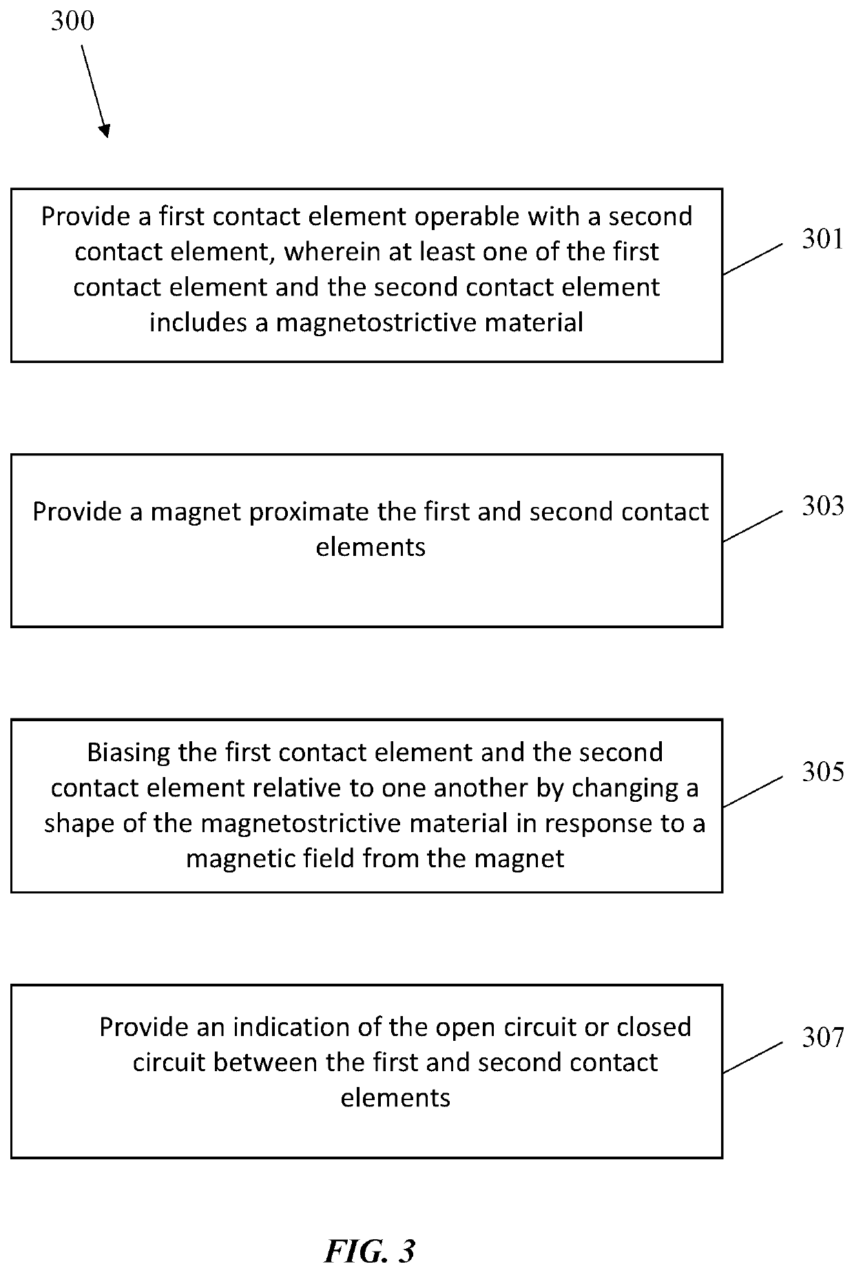
However, with conventional reed switches, there is not enough magnetic material to sustain a large enough magnetic field to generate sufficient contact force to give a low contact resistance.

Method used


Image

  • Magnetically activated switch having magnetostrictive material
  • Magnetically activated switch having magnetostrictive material
  • Magnetically activated switch having magnetostrictive material

Examples


Embodiment Construction

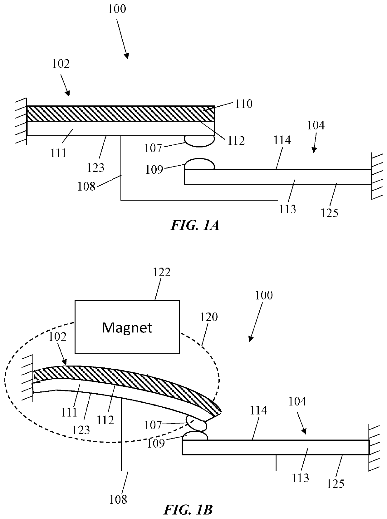
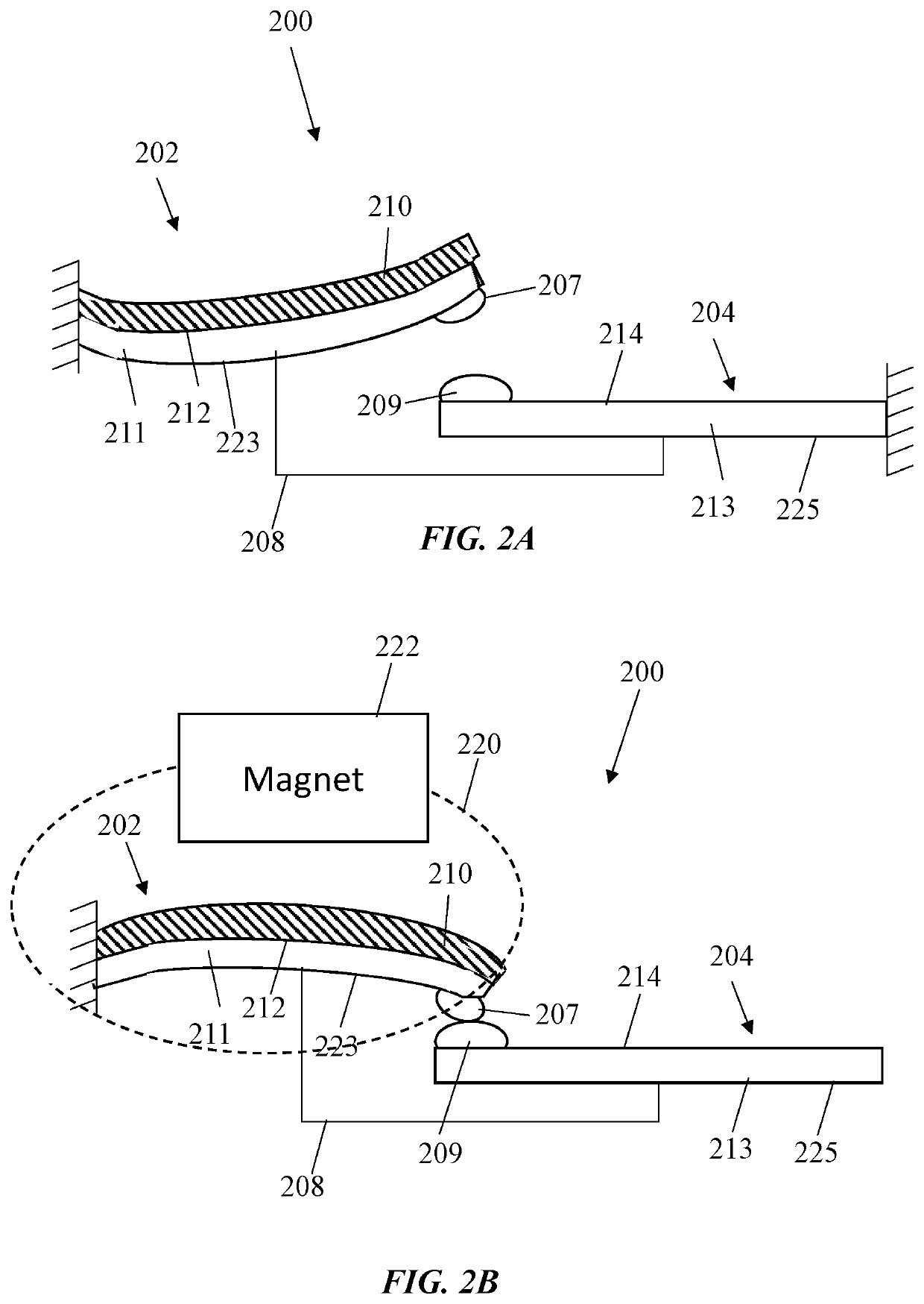
[0018]The present disclosure will now proceed with reference to the accompanying drawings, in which various approaches are shown. It will be appreciated, however, that the switch assembly may be embodied in many different forms and should not be construed as limited to the approaches set forth herein. Rather, these approaches are provided so that this disclosure will be thorough and complete, and will fully convey the scope of the disclosure to those skilled in the art. In the drawings, like numbers refer to like elements throughout.

[0019]As used herein, an element or operation recited in the singular and proceeded with the word “a” or “an” should be understood as not excluding plural elements or operations, unless such exclusion is explicitly recited. Furthermore, references to “one approach” or “one embodiment” of the present disclosure are not intended to be interpreted as excluding the existence of additional approaches and embodiments that also incorporate the recited features....


PUM


Abstract

Switch assemblies and a switching method are disclosed. In some embodiments, a switch assembly may include a first contact element, and a second contact element operable with the first contact element. The first and second contact elements form an open circuit in a first configuration and form a closed circuit in a second configuration. At least one of the first contact element and the second contact element includes a magnetostrictive material. During operation, a magnetic field from a magnet causes the magnetostrictive material to deform or change shape/dimensions, thus causing the first and second contact elements to open or close. In some embodiments, the switch assembly is a micro-electro-mechanical-system (MEMS) switch.

Description

BACKGROUND OF THE DISCLOSUREField of the Disclosure[0001]This disclosure relates generally to the field of switches and, more particularly, to magnetically activated switches having magnetostrictive material.Discussion of Related Art[0002]A number of different types of magnetic proximity switches utilizing reed switches or similar contact configurations for actuation in response to a magnetic field are presently known. Early types of magnetic switches consist of a pair of contacts formed of magnetic material and physically disposed relative to a magnet to achieve a desired switch position. More specifically, reed switches are operated by the magnetic field of an energized coil or a permanent magnet, which induces north (N) and south (S) poles on the reeds. The reed contacts are closed / opened by this magnetic attractive force. When the magnetic field is removed, the reed elasticity causes the contacts to open / close the circuit.[0003]One of the key parameters of a switch is the contac...

Claims


Application Information

Patent Timeline
Patent Type & Authority Applications(United States)
IPC IPC(8): H01H36/00
CPCH01H36/00H01H2036/0093H01H55/00H01H37/58
Inventor JOHNSON, BRIAN
Owner LITTELFUSE INC
Why Eureka
Try Eureka