Reducing or eliminating routing microloops in networks having a clos topology, such as data center clos networks employing the exterior border gateway protocol (EBGP) for example

a topology and network technology, applied in the field of networks having a clos topology, can solve the problems of inconsistent latency, unsuitable for many current data centers, limitations on scalability and limitations of the spanning tree protocol (stp), etc., and achieve the effect of avoiding discarding or otherwise dropping packets

Active Publication Date: 2019-11-28
JUMIPER NETWORKS INC
View PDF0 Cites 35 Cited by
  • Summary
  • Abstract
  • Description
  • Claims
  • Application Information

AI Technical Summary

Benefits of technology

[0027]Thus, the solution to routing micro-loops proposed in RFC 7928 discards packets rather than having them loop. This can be considered a “lesser of two evils” approach. Clearly, it would be useful if routing micro-loops could be avoided in a better way (e.g., in a way that avoids discarding or otherwise dropping packets).

Problems solved by technology

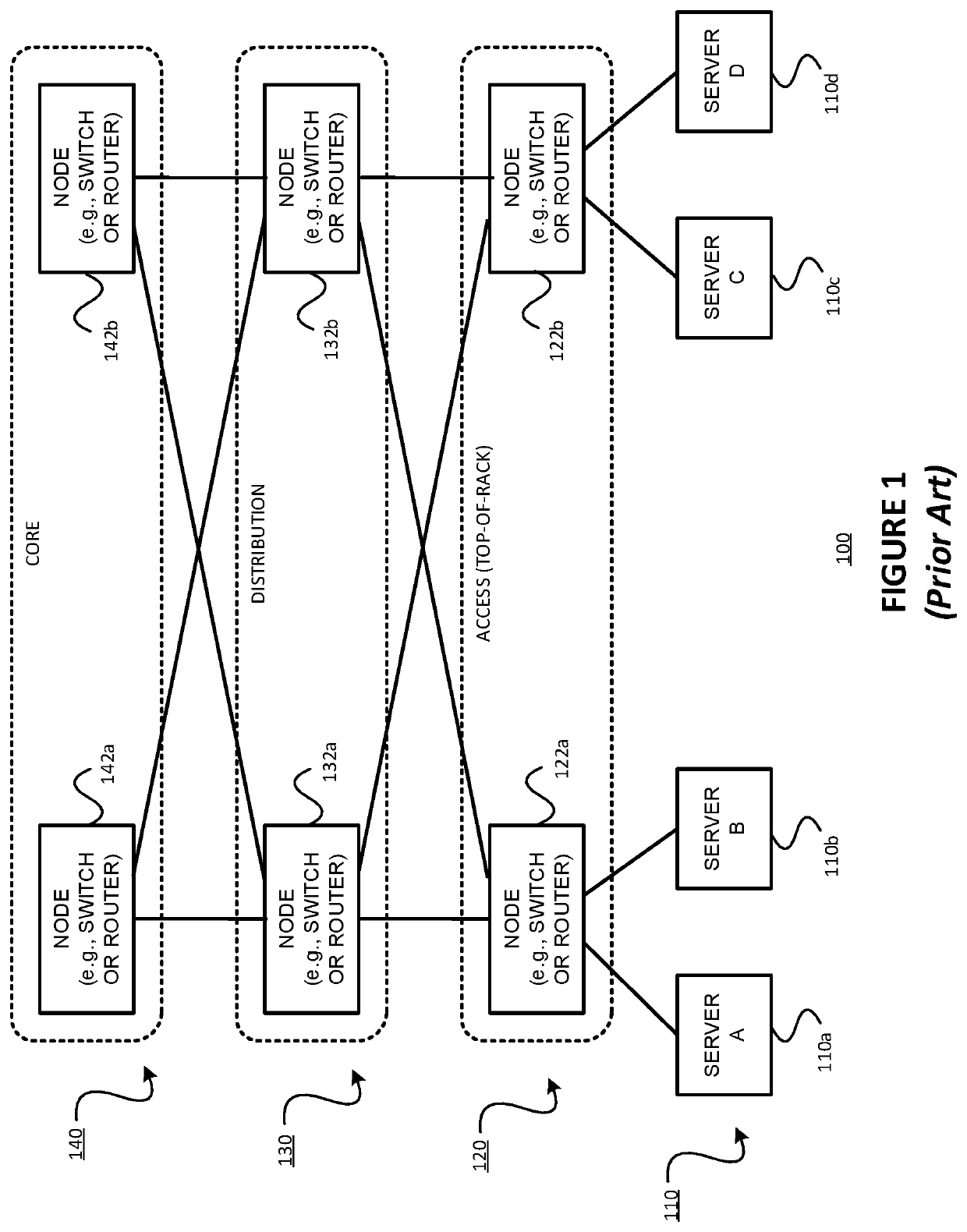
Unfortunately, there are a number of drawbacks of this traditional network architecture 100 which make it unsuitable for many current data centers.
Such drawbacks include inconsistent latency (due to different numbers of hops between source and destination servers), limitations on scalability and limitations of the spanning tree protocol (STP).
In data center networks, the consistency of these two related parameters has become more critical than before, and the classic tree-based architecture such as that of FIG. 1 does not provide such consistency.
When the data center grows, the traditional data center network architecture 100 may be unable to scale due to port / card / device / bandwidth limitations.
However, even when using these technologies, scalability can still be an issue.
It is not possible to bond more than two switches (this is supported only with various limitations).
Vendor dependency is another disadvantage, as most of these protocols are vendor proprietary.
Finally, these vendor-specific protocols might not operate well with one another.
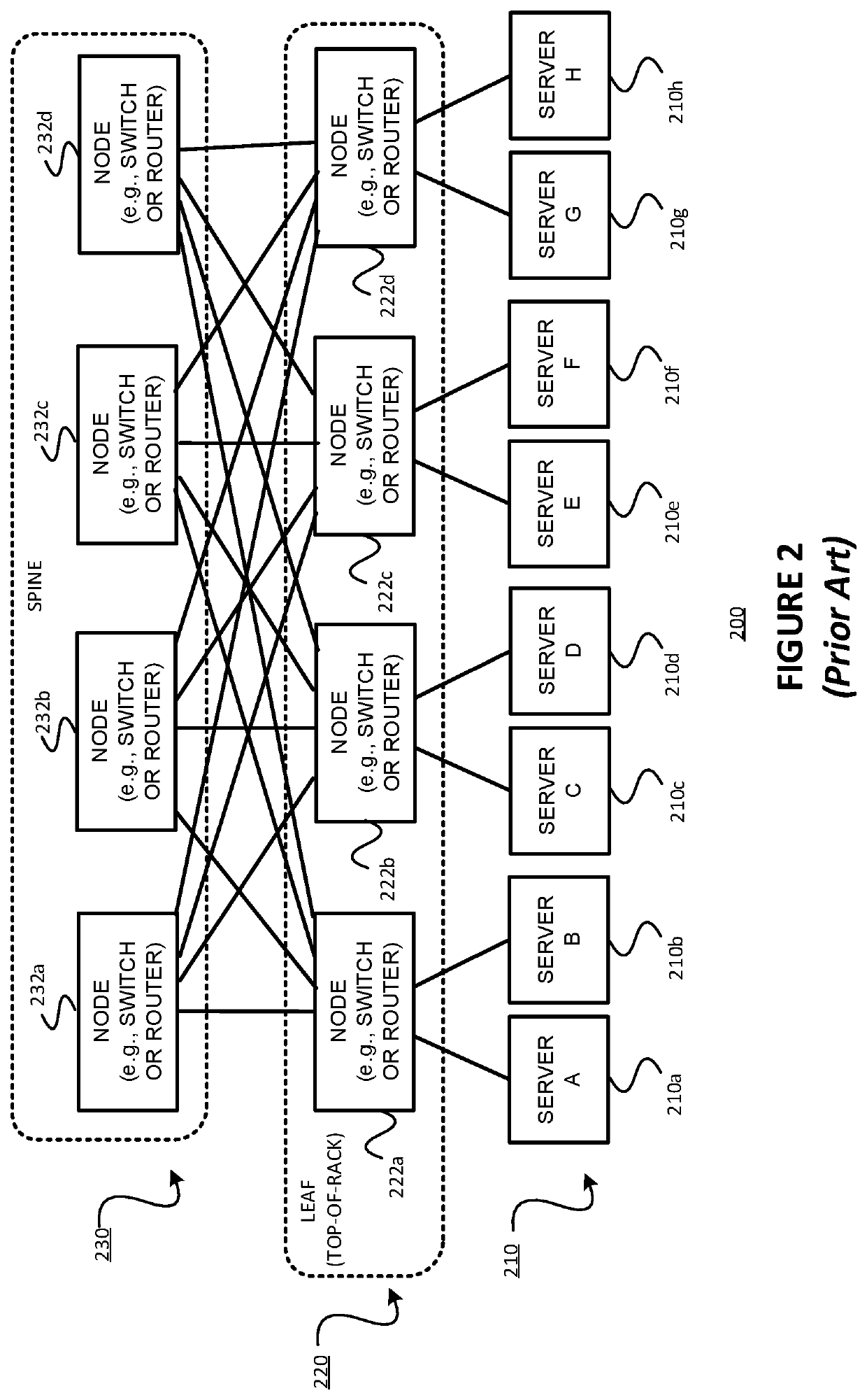
On the other hand, as the connectivity matrix is quite complex in this topology, failures can be handled gracefully.
Third, the CLOS topology scales horizontally, which is very cost effective.
For example, in general, the size of L2 domains should be limited due to the difficulty in troubleshooting L2 environments.
There is also the risk of broadcast storms in large L2 domains, and MLAG is vendor dependent.
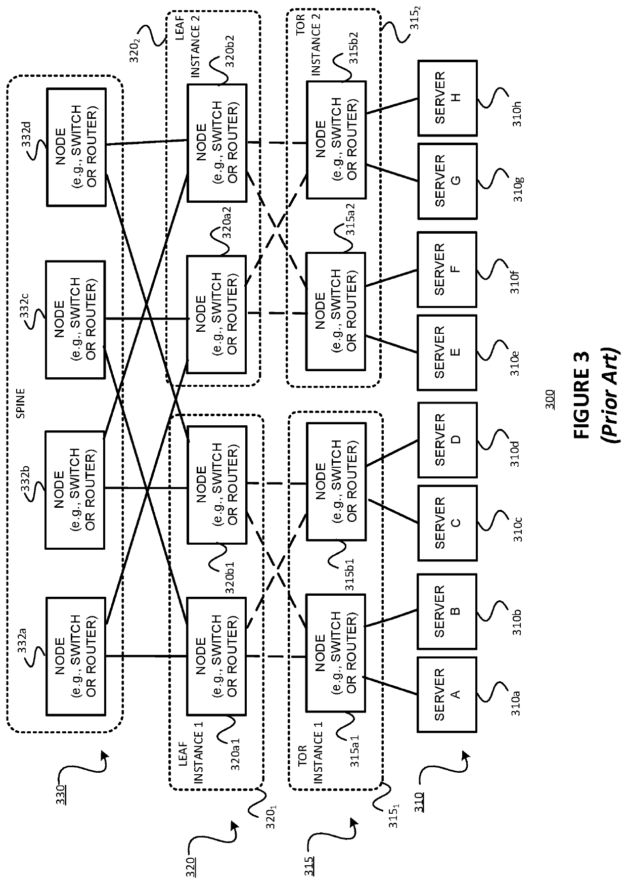
This introduces limitations such as being able to use only two leaves in one instance.
As to whether to use interior BGP (iBGP) or eBGP, route reflection between nodes can cause problems if iBGP is used.
More specifically, spine switches can be declared as route reflectors, but can be problematic if ECMP paths are desired since route reflectors reflect only the best paths.
However, this would be more challenging if each leaf node 320a1′-320b2′ has its own AS number, and / or if servers are connected to more than one TOR node for redundancy.

Method used


Image

  • Reducing or eliminating routing microloops in networks having a clos topology, such as data center clos networks employing the exterior border gateway protocol (EBGP) for example
  • Reducing or eliminating routing microloops in networks having a clos topology, such as data center clos networks employing the exterior border gateway protocol (EBGP) for example
  • Reducing or eliminating routing microloops in networks having a clos topology, such as data center clos networks employing the exterior border gateway protocol (EBGP) for example

Examples


Embodiment Construction

[0044]The present disclosure may involve novel methods, apparatus, message formats, and / or data structures for reducing or eliminating routing micro-loops in networks having a CLOS topology, such as data center CLOS networks employing the exterior border gateway protocol (eBGP) for example. The following description is presented to enable one skilled in the art to make and use the described embodiments, and is provided in the context of particular applications and their requirements. Thus, the following description of example embodiments provides illustration and description, but is not intended to be exhaustive or to limit the present disclosure to the precise form disclosed. Various modifications to the disclosed embodiments will be apparent to those skilled in the art, and the general principles set forth below may be applied to other embodiments and applications. For example, although a series of acts may be described with reference to a flow diagram, the order of acts may diffe...


PUM


Abstract

The problem of routing micro-loops in networks having a CLOS topology, such as data center CLOS networks employing the exterior border gateway protocol (eBGP) for example, is solved by: (a) receiving, on an interface of one of the nodes, a datagram, the datagram including destination information; (b) determining a next hop and an egress interface using (1) an identifier of the interface on which the datagram was received, (2) the destination information of the received datagram, and (3) stored forwarding information such that a routing micro-loop is avoided without discarding the datagram; and (c) forwarding the datagram via the egress interface. For example, this problem may be solved by (a) receiving, on an interface a node of the CLOS network, a datagram, the datagram including destination information; (b) looking up, using the destination information of the received datagram and stored forwarding information, a next hop egress interface on the node; (c) determining whether or not the next hop egress interface on the node is the same as the interface on which the datagram was received; and (d) responsive to a determination that the next hop egress interface on the node is the same as the interface on which the datagram was received, (1) replacing the next hop egress interface with a safe multipath next hop egress interface, and (2) forwarding the datagram via the safe multipath next hop egress interface, and otherwise, responsive to a determination that the next hop egress interface on the node is not the same at the interface on which the datagram was received, simply forwarding the datagram via the next hop egress interface.

Description

§ 1. BACKGROUND OF THE INVENTION§ 1.1 Field of the Invention[0001]The present disclosure concerns networks having a CLOS topology, such as networks used in data centers for allowing servers to communicate with one another. More specifically, the present disclosure concerns the potential problem of routing micro-loops in the event of a failed link (or a failed interface or a failed node terminating a link, all of which are commonly referred to as a “failed link” absent further specificity) in a CLOS network.§ 1.2 Background Information[0002]The trend towards using CLOS network topology in data center networks, as well as the trend towards using the exterior Border Gateway Protocol (eBGP) for routing in such networks, are described in this section. More details as to the reasons behind these trends can be found in Request for Comments 7938, “Use of BGP for Routing in Large-Scale Data Centers” (Internet Engineering Task Force (IETF), August 2016) (referred to as “RFC 7938” and incorpor...

Claims


Application Information

Patent Timeline
Patent Type & Authority Applications(United States)
IPC IPC(8): H04L12/703H04L12/705H04L12/751H04L12/733H04L12/707H04L12/715H04L12/741H04L12/933H04L45/24H04L45/28H04L45/50H04L45/02H04L45/122H04L45/18H04L45/74
CPCH04L45/18H04L45/50H04L45/22H04L45/033H04L45/745H04L45/02H04L45/04H04L45/20H04L45/24H04L45/28H04L49/1515
Inventor DJERNAES, MARTIN
Owner JUMIPER NETWORKS INC
Why Eureka
Try Eureka