Eureka AIR delivers breakthrough ideas for toughest innovation challenges, trusted by R&D personnel around the world.

Electric mop

Inactive Publication Date: 2019-12-05
SHENZHEN FCY TECH
View PDF5 Cites 0 Cited by
  • Summary
  • Abstract
  • Description
  • Claims
  • Application Information

AI Technical Summary

Benefits of technology

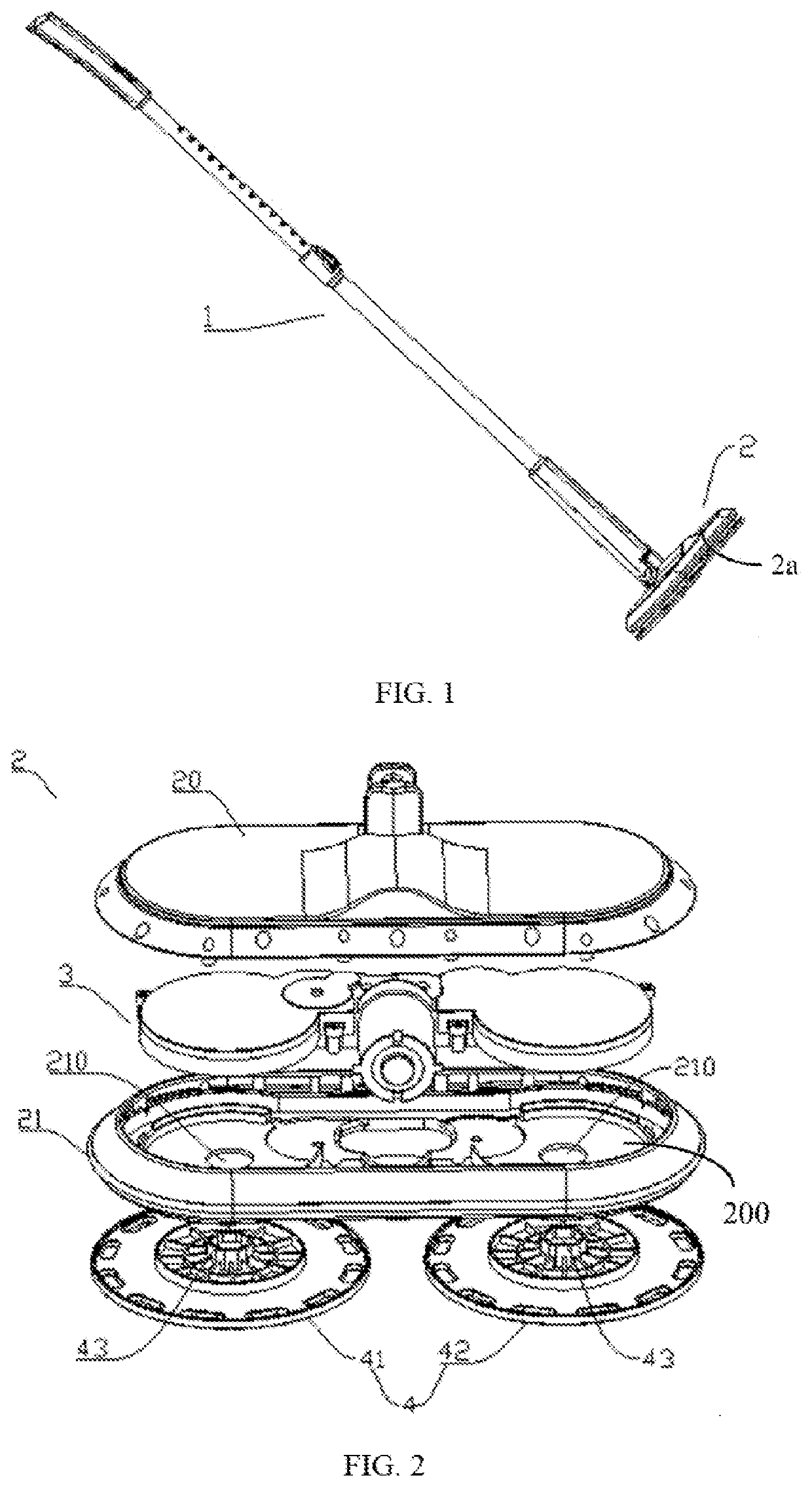
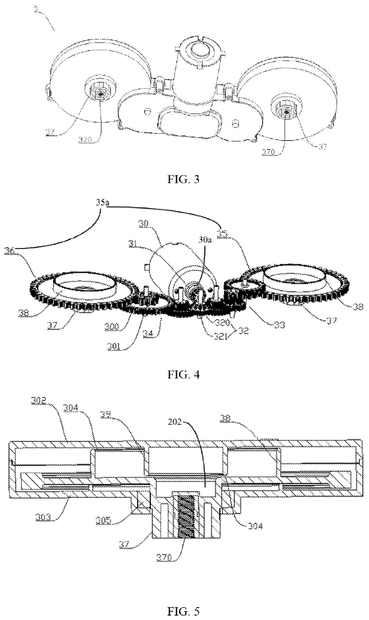
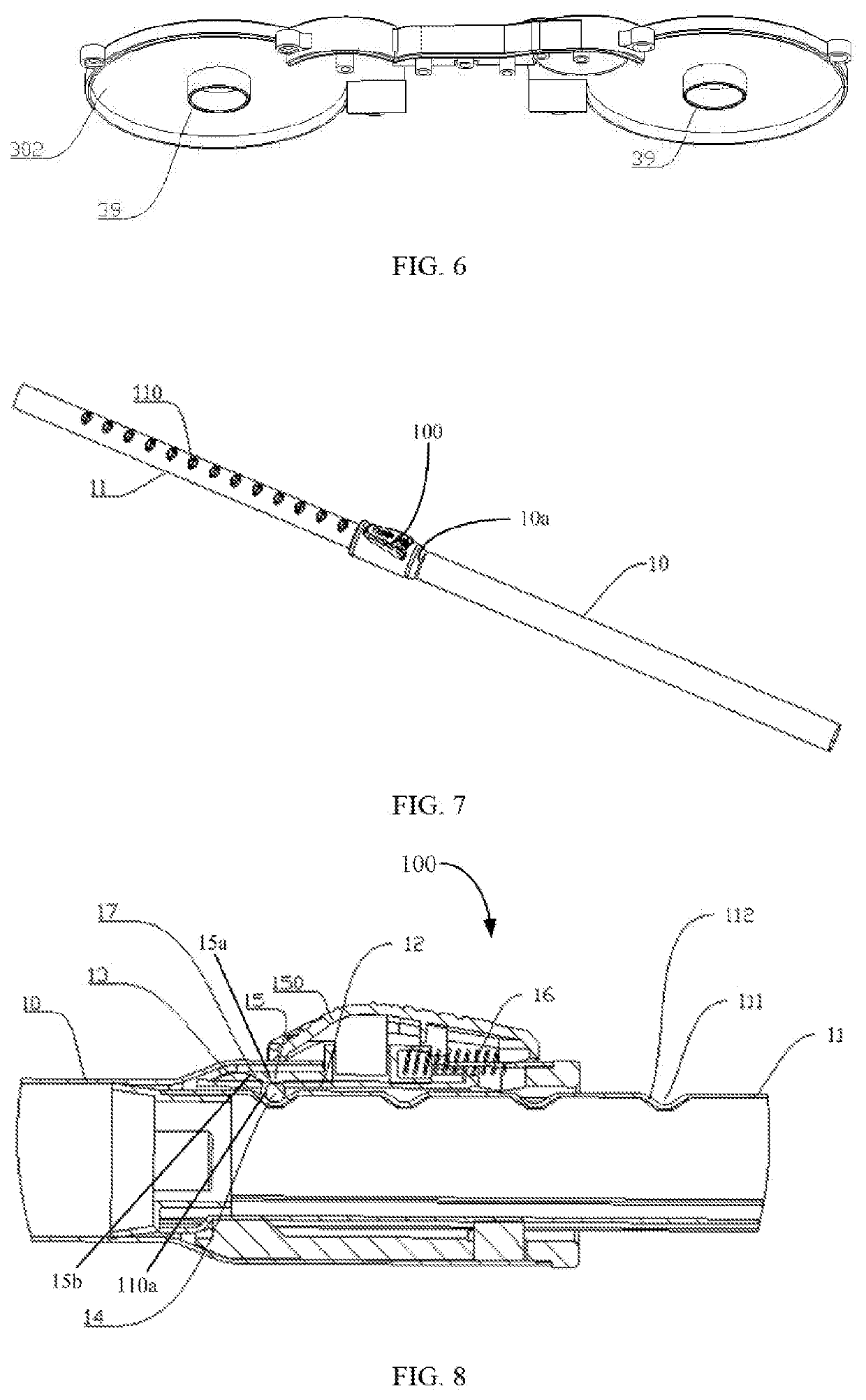
The patent describes a structure for an electric mop with two cleaning parts that can rotate forward and backward. This structure allows for balanced and steady control of the mop by reducing forces on the user. The two cleaning parts provide a large cleaning surface and can clean corners easily with one part.

Problems solved by technology

However, a conventional electric mop has only one cleaning member so that the clean way is too single, which is not optionally adjusted according to actual demands.
In addition,the one cleaning member can only rotate towards a single direction when the electric mop is operated to clean the ground so that it is difficult for the user to maintain the balance of the electric mop.

Method used


Image

  • Electric mop
  • Electric mop
  • Electric mop

Examples


Embodiment Construction

[0037]The disclosure is illustrated by way of example and not by way of limitation the figures of the accompanying drawings, in which like reference numerals indicate similar elements.

[0038]According to the described exemplary embodiment of the present disclosure, all other embodiments obtained by one of ordinary skill in the related art without the need for a creative labor are within the protection scope of the present disclosure. Unless defined otherwise, the technical terms or scientific terms used in the present disclosure shall be a general meaning commonly understood by those having ordinary skill in the related art which the present disclosure is applied.

[0039]In the description of the present disclosure, the terms such as “first” and “second” shown in the specification are only used to describe, but not indicated that the elements of the present disclosure is important or represented the amount of the elements. That is, the features limited by the terms of “first” and “seco...


PUM


Abstract

An electric mop includes a handle, a flopping member connected to the handle. The mopping member includes a driving member with an output thereof connected to a pair of cleaning portions. The driving member includes a motor with an output shaft thereof connected to a driving bevel gear, a reversing gear formed a right-angle transmission relationship with the driving bevel gear, and a pair of cylindrical gear groups respectively connected to the pair of cleaning portions. The difference between the number of cylindrical gears of the two groups is singular. The structure drives the two cleaning portions respectively rotation forward and backward by the driving member so that force of the two cleaning portions can be offset each other for users to keep balance and steadily control a moving direction of the electric mop, the two cleaning portions are provided for ensuring a large cleaning surface and cleaning some corners.

Description

BACKGROUND1. Technical Field[0001]The present disclosure generally relates to cleaning devices field, and especially relates to an electric mop.2.Description of Related Art[0002]A conventional electric mop generally includes a handle, a mopping member, a cleaning member fixed with the mopping member and a driving member electrically connected to a power supply to drive the cleaning member rotate to clean the ground. However, a conventional electric mop has only one cleaning member so that the clean way is too single, which is not optionally adjusted according to actual demands. In addition,the one cleaning member can only rotate towards a single direction when the electric mop is operated to clean the ground so that it is difficult for the user to maintain the balance of the electric mop.SUMMARY[0003]The technical problems to be solved: in view of the shortcomings of the related art, the present disclosure relates to an electric mop which can drive two cleaning portions respectively...

Claims


Application Information

Patent Timeline
IPC IPC(8): A47L11/14A47L11/40
CPCA47L11/4069A47L11/14A47L11/4038A47L11/08A47L11/16A47L11/283A47L11/4075
Inventor TAO, ZHIMINGWU, ZHENYUCHEN, XIAOMAO
Owner SHENZHEN FCY TECH
Why Eureka
Eureka Blog
Learn More