Flat data transmission cable

a data transmission cable and flat technology, applied in flat/ribbon cables, insulated conductors, cables, etc., can solve the problems of reducing the assembly efficiency of terminal equipment, increasing the assembly procedure, and increasing the cost of equipmen

Active Publication Date: 2019-12-05
ALLTOP ELECTRONICS SU ZHOU
View PDF6 Cites 0 Cited by
  • Summary
  • Abstract
  • Description
  • Claims
  • Application Information

AI Technical Summary

Benefits of technology

The patent text is about a new type of data transmission cable that has wires placed very close together and a layer of plastic and metal all in one. The cable has a bend in it and is designed to have a consistent angle between two sections on either side of the bend. This makes it easier to bend the cable and send data through it.

Problems solved by technology

However, when bending operation is carried out, because there are many cables inside the equipment, various bending modes should be considered, which results in greatly reducing the assembly efficiency of the terminal equipment.
When bending portions more, clamps are found inside the equipment, the assembly procedure is increased and the cost of the equipment is higher.

Method used


Image

  • Flat data transmission cable
  • Flat data transmission cable
  • Flat data transmission cable

Examples


first embodiment

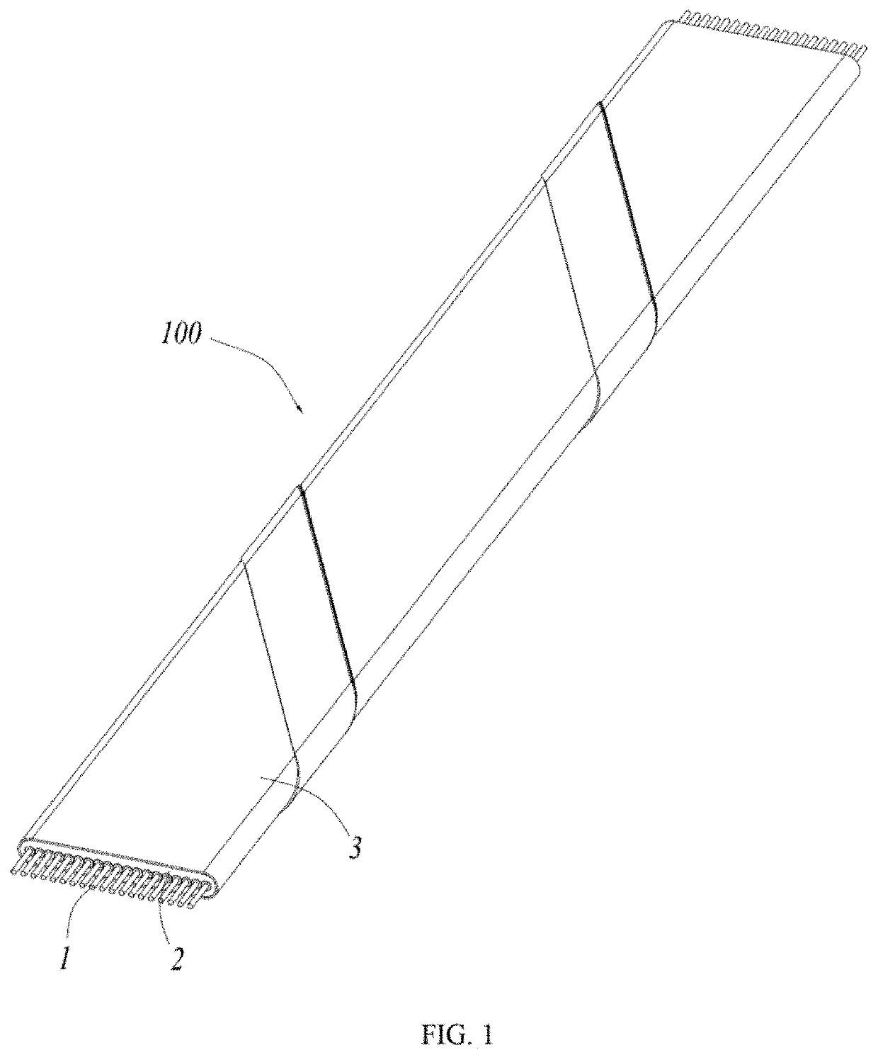
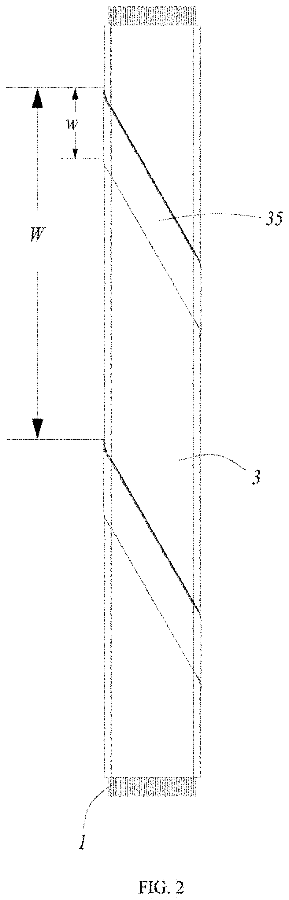
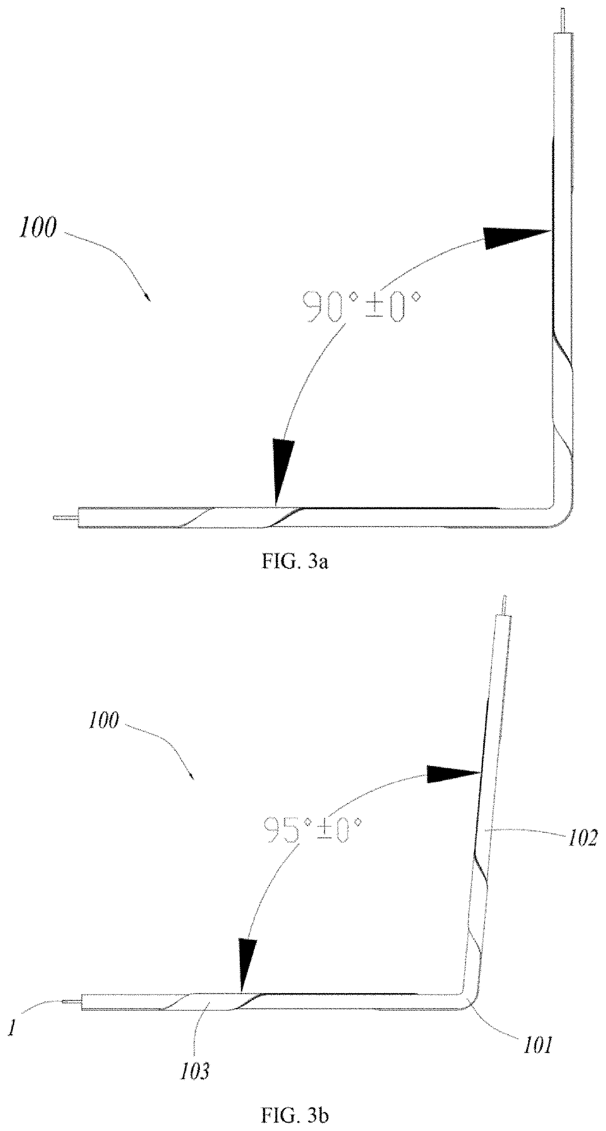
[0020]Referring to FIGS. 1 to 7, the present disclosure discloses a data transmission cable 100, a state diagram of the data transmission cable 100 before bending is shown in FIGS. 1 to 2, and an actual state diagram of the data transmission cable 100 after bending is shown in FIGS. 4 to 5.

[0021]Conjunction with FIGS. 1 to 7, the data transmission cable 100 comprises a plurality of juxtaposed wires 1, a plastic layer 2 enclosing on the wires 1 integrally and a metallic layer 3 formed by a metal material belt arranged on an outer side of the plastic layer 2 in a spiral winding way.

[0022]Conjunction with FIGS. 1 to 5, in the present embodiment, each wire 1 has a conductor 11 and an insulative cladding layer 12 enclosing on the conductor 11. Central axes of the conductors 11 are located on a same plane, the plastic layer 2 is enclosing on the cladding layers 12 to form a common single insulation layer. The plastic layer 2 defines a top surface and a bottom surface parallel to the plane...

second embodiment

[0028]the present disclosure is disclosed in FIG. 8, each wire 1 also can have only the conductor 11 without the cladding layer 12, that is, the plastic layer 2 is directly enclosing on the wires 1, and the same effect can be achieved. By adopting the setting, the thickness of the plastic layer 2 can be further reduced, and the overall thickness of the data transmission cable 100 can be further reduced.

[0029]In further, the wires 1 are disposed in an equally spaced arrangement in present embodiment, and in the arrangement direction of the wires 1, the number of the wires 1 is in the range of 3 to 50. The wires 1 define at least two grounding wires and at least a signal wire between the two grounding wires. Therefore, the interference around the signal wire can be eliminated by grounding wire, and the signal transmission environment of the signal wire can be guaranteed, thereby improving the efficiency and stability of signal transmission.

[0030]As a preferred embodiment of the presen...


PUM


Abstract

A flat data transmission cable includes a plurality of juxtaposed wires, a plastic layer enclosing on the wires integrally and a metallic layer formed by a metal material belt arranged on an outer side of the plastic layer in a spiral winding way. In the length direction of the data transmission cable, the data transmission cable has at least one bending portion, the data transmission cable is formed with a first section and a second section on both sides of the bending portion, and a stable bending angle is formed between the first section and the second section.

Description

CROSS REFERENCE TO RELATED APPLICATIONS[0001]The present application claims the priority of Chinese Patent Application No. 201810556982.0 filed on Jun. 1, 2018, Chinese Patent Application No. 201821730509.1 filed on Oct. 24, 2018 and Chinese Patent Application No. 201821732499.5 filed on Oct. 24, 2018, the contents of which are hereby incorporated by reference into this application.BACKGROUND1. Technical Field[0002]The present disclosure relates to a data transmission cable, and more particularly to a flat data transmission cable having better high frequency performance.2. Description of Related Art[0003]In the 3C industry, a transmission cable can be used as a medium for an electrical connection between two electronic devices and can carry out the expected signal transmission stably. Therefore, the transmission cable is widely used in various electronic devices. In particular, transmission cables connected with USB, HDMI, DVI, Displayport and other types of connector has a performa...

Claims


Application Information

Patent Timeline
IPC IPC(8): H01B7/08H01B7/02H01B7/04H01B7/22H01B7/295H01B7/00
CPCH01B7/295H01B7/0225H01B7/04H01B7/0054H01B7/228H01B7/0853H01B7/02H01B7/0823H01B7/0861H01B7/17H01B7/226H01B11/00H01B7/0208H01B7/0241H01B7/205H01B11/203H01R12/53H05K1/111H05K1/117H05K2201/09027H05K2201/094H05K2201/10356
Inventor NI, MINDICHEN, YICHANG
Owner ALLTOP ELECTRONICS SU ZHOU
Why Eureka
Try Eureka