High-speed connector on high-density mini version chip side

a high-speed, mini-type technology, applied in the direction of connection, electrical apparatus, coupling device connection, etc., can solve the problems of wasting space on printed circuit board, utilizing redundant space below, etc., to achieve the effect of increasing data processing and transmission speed, improving the performance and device density of the corresponding server, workstations and cpus in i/o memory synchronously, and improving the heat dissipation of servers

Active Publication Date: 2019-12-05
LUXSHARE TECH INT INC
View PDF0 Cites 14 Cited by
  • Summary
  • Abstract
  • Description
  • Claims
  • Application Information

AI Technical Summary

Benefits of technology

[0004]With the increase of the network age, the requirements on data processing and transmission speed are increased, the performance and device density of the corresponding servers, workstations and CPUs in the I / O memory are synchronously improved, and certain challenges are brought to the device size and the heat dissipation of the servers. Generally, the heat sink occupies a large space on the printed circuit board, and the space between the heat sink and the printed circuit board in the height direction is small, such that the conventional connector cannot be arranged below the heat sink, and it is difficult to utilize the redundant space below the heat sink, resulting in wasted space of the printed circuit board is wasted.
[0005]The present invention provides a high-speed connector on a high-density MINI version chip side, which has small size and the height of less than 3.7 mm, can be placed under a heat sink of a chip, and has the transmission speed up to 56 Gbit / s. The space of the board end is utilized to the maximum extent, and the problem that the CPU occupies the space of the board end due to the size expansion of the radiating module is solved.

Problems solved by technology

Generally, the heat sink occupies a large space on the printed circuit board, and the space between the heat sink and the printed circuit board in the height direction is small, such that the conventional connector cannot be arranged below the heat sink, and it is difficult to utilize the redundant space below the heat sink, resulting in wasted space of the printed circuit board is wasted.

Method used


Image

  • High-speed connector on high-density mini version chip side
  • High-speed connector on high-density mini version chip side
  • High-speed connector on high-density mini version chip side

Examples


Embodiment Construction

[0038]The structural principle and the operational principle of the present invention will be described in detail below with reference to the attached drawings:

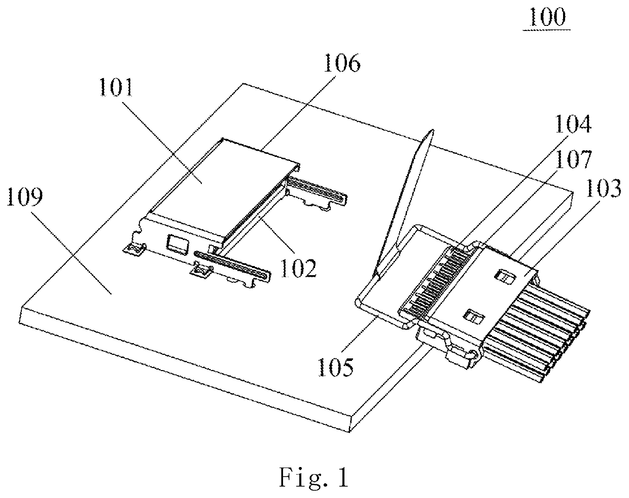
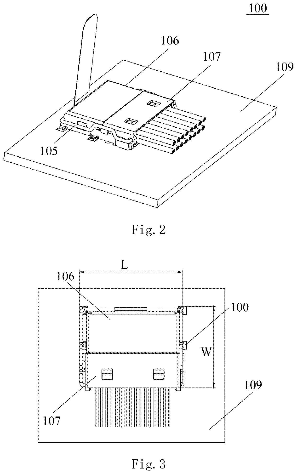
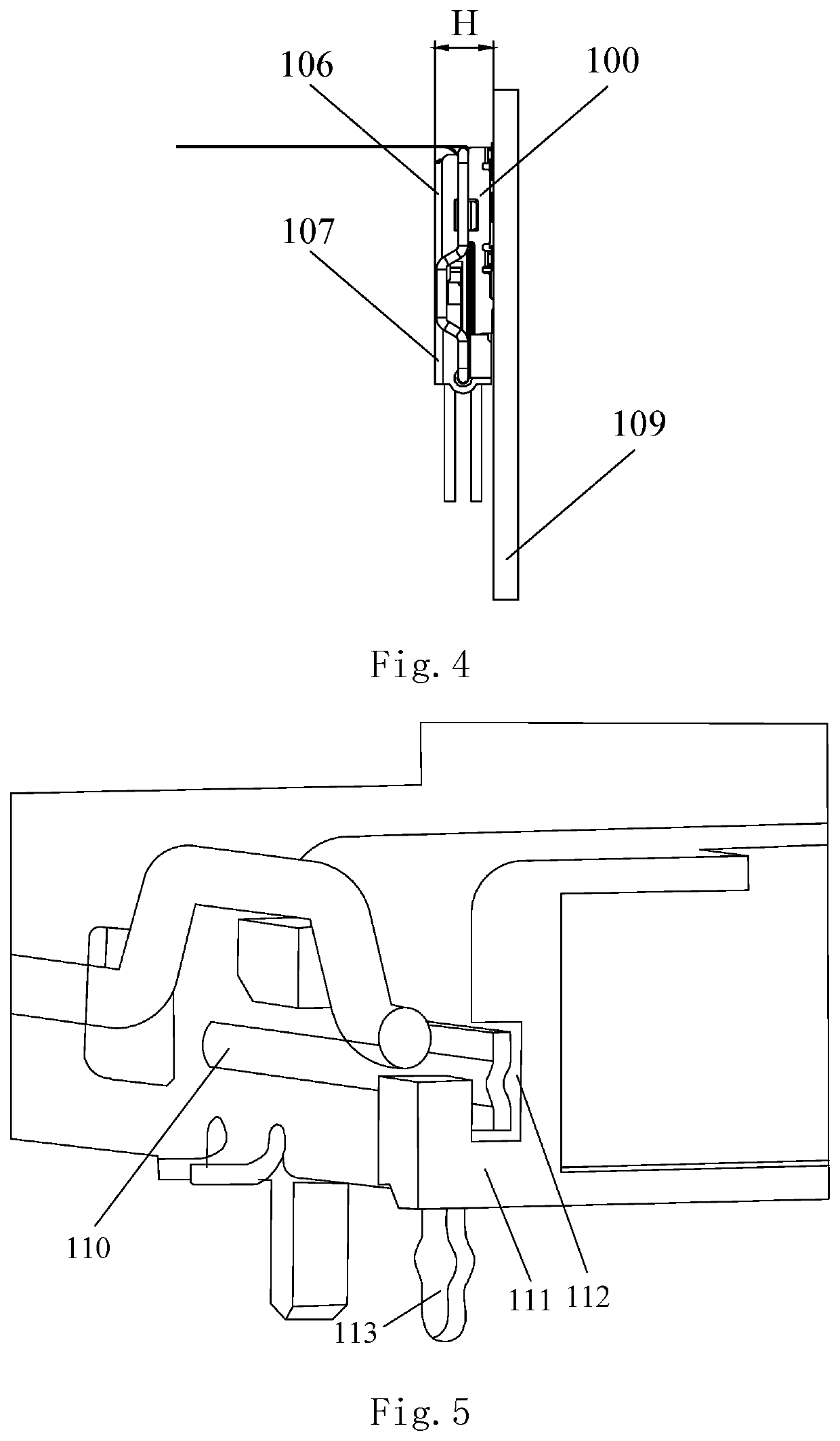
[0039]FIG. 1 is a perspective view showing the connector of the present invention in separated state. As shown in FIG. 1, the high-speed connector 100 on high density MINI version chip side of the present invention includes a board end connector 106, a wire end connector 107 and a printed circuit board 109. Both of the board end connector 106 and the wire end connector 107 are used cooperatively.

[0040]The board end connector 106 is mounted on the printed circuit board 109 and comprises a board end connector shell 101 and a board end connector body 102 embedded in the board end connector shell 101.

[0041]The wire end connector 107 comprises a wire end case 103, a tongue plate 104, a wire end body (not shown) and an unlocking snap 105. The tongue plate 104 is covered by the wire end body, the wire end case 103 covers the wire en...


PUM


Abstract

The present invention provides a high-speed connector on a high density MINI version chip side, which comprises a board end connector, a wire end connector and a printed circuit board; the board end connector is arranged on the printed circuit board; the board end connector comprises a board end connector shell and a board end connector body arranged in the board end connector shell; the wire end connector comprises a wire end case and a tongue plate fixed to the wire end case; wherein at least one guide piece is extended from the board end connector shell, and the wire end case is provided with at least one guide slot for creating a butt joint with the guide piece. The connector of the present invention utilizes the space of the board end to the maximum extent, solves the problem that the CPU occupies the space of the board end due to the increased size of the heat dissipation module, and can realize high-speed data transmission.

Description

CROSS-REFERENCE TO RELATED APPLICATIONS[0001]This non-provisional application claims priority under 35 U.S.C. § 119(a) on Patent Application No. 201820826642.0 filed in P.R. China on May 30, 2018, the entire contents of which are hereby incorporated by reference.[0002]Some references, if any, which may include patents, patent applications and various publications, may be cited and discussed in the description of this invention. The citation and / or discussion of such references, if any, is provided merely to clarify the description of the present invention and is not an admission that any such reference is “prior art” to the invention described herein. All references listed, cited and / or discussed in this specification are incorporated herein by reference in their entireties and to the same extent as if each reference was individually incorporated by reference.TECHNICAL FIELD[0003]The present invention relates to a connector, in particular to a high-speed connector on the chip side o...

Claims


Application Information

Patent Timeline
Patent Type & Authority Applications(United States)
IPC IPC(8): H01R12/70H01R12/79H01R12/58
CPCH01R12/7023H01R12/58H01R12/79H01R12/7029H01R12/716H01R13/2428
Inventor HUANG, BINLI, TIESHENGCHEN, HONGJILIU, KUN
Owner LUXSHARE TECH INT INC
Why Eureka
Try Eureka