Eureka AIR delivers breakthrough ideas for toughest innovation challenges, trusted by R&D personnel around the world.

Routing and control protocol for high-performance interconnect fabrics

Inactive Publication Date: 2019-12-05
LIGHTFLEET CORP
View PDF3 Cites 3 Cited by
  • Summary
  • Abstract
  • Description
  • Claims
  • Application Information

AI Technical Summary

Benefits of technology

The disclosure describes a flow control protocol for a state machine that can switch between a default interrupt mode and a transient switching mode. In the default mode, the arbiter selects the highest priority flit for data transfer, but if there are higher priority flits that may interrupt the selected channel, the arbiter can switch to the transient mode to hold open a channel for the higher priority flits. This allows for seamless control with low latency. The protocol includes an interleave mechanism to insert a CRC code to temporarily hold open a channel until the desired data transfer is complete.

Problems solved by technology

A problem with this parallel processing has been that the multiple processors need to be able to seamlessly communicate data and control signals.
One unsatisfactory approach is a bus-based interconnect.
However, such an interconnect approach is not scalable beyond a modest number of processors and / or chips.
Other disadvantages of this approach have been relatively high cost, and when the scale increases sufficiently excessive bulk and even heat.
However, a disadvantage of this approach is that there are performance issues especially with regard to control and latency.
Heretofore, the requirement(s) of seamless communication, economy, compact form factor, energy efficiency while avoiding control and latency issues referred to above have not been fully met.

Method used


Image

  • Routing and control protocol for high-performance interconnect fabrics
  • Routing and control protocol for high-performance interconnect fabrics
  • Routing and control protocol for high-performance interconnect fabrics

Examples


Embodiment Construction

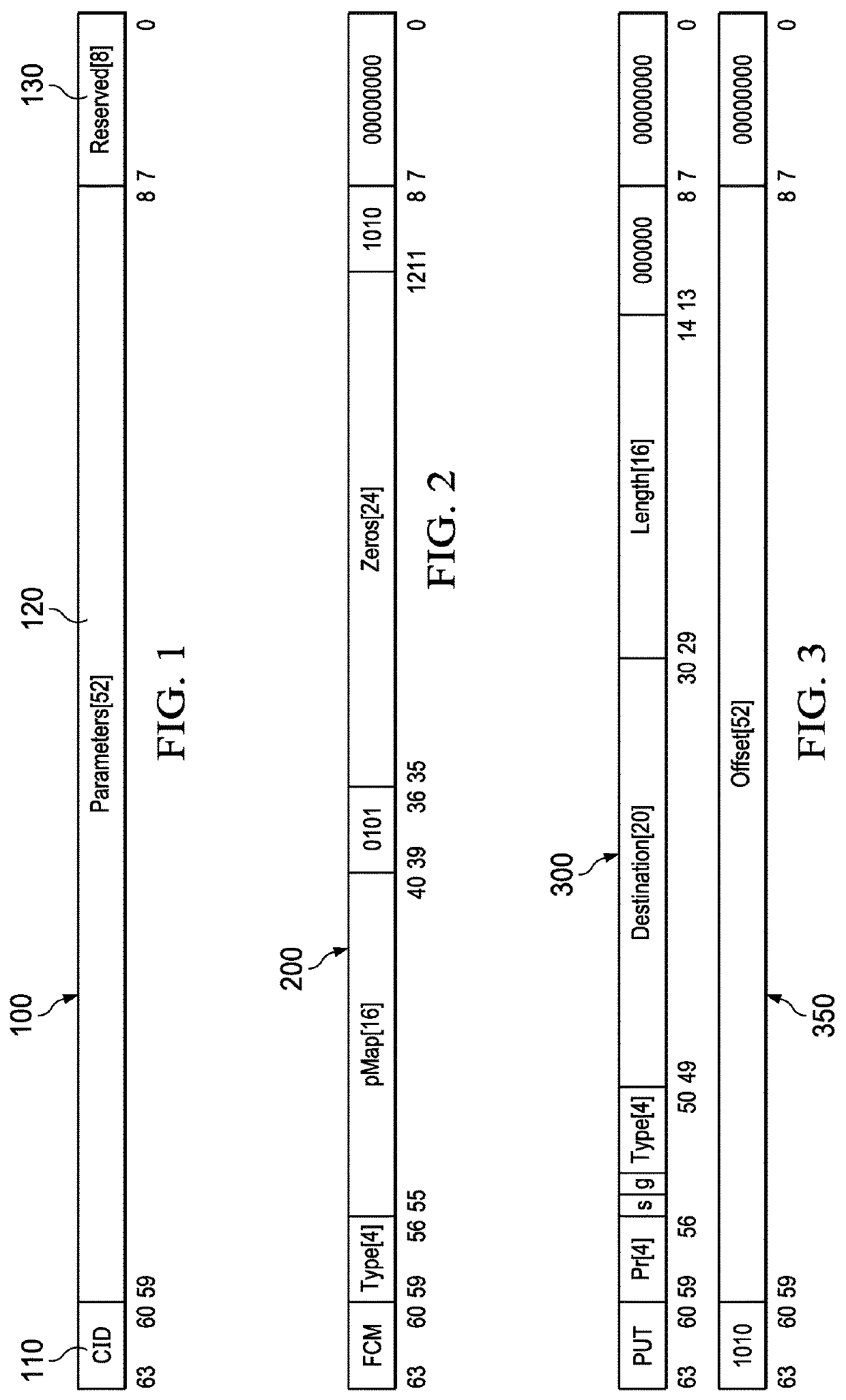
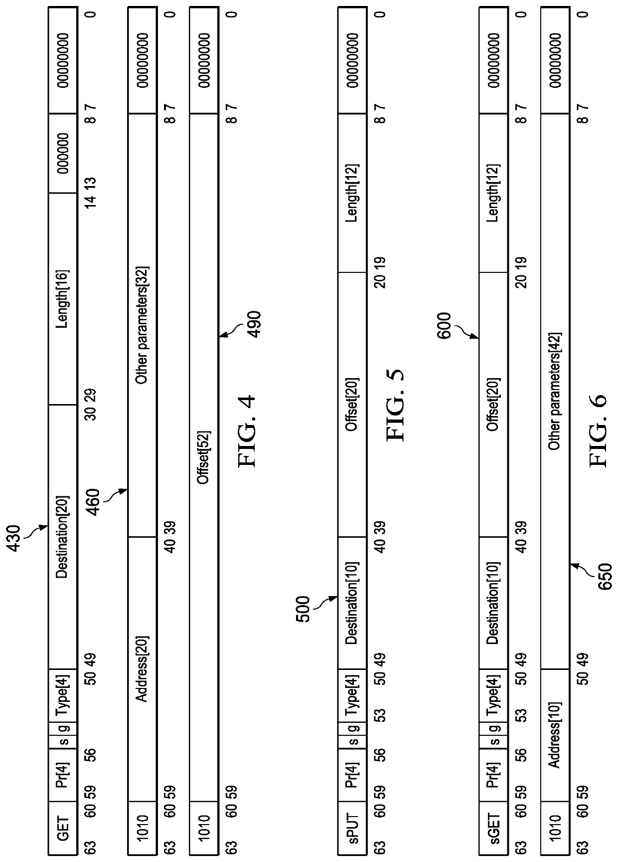
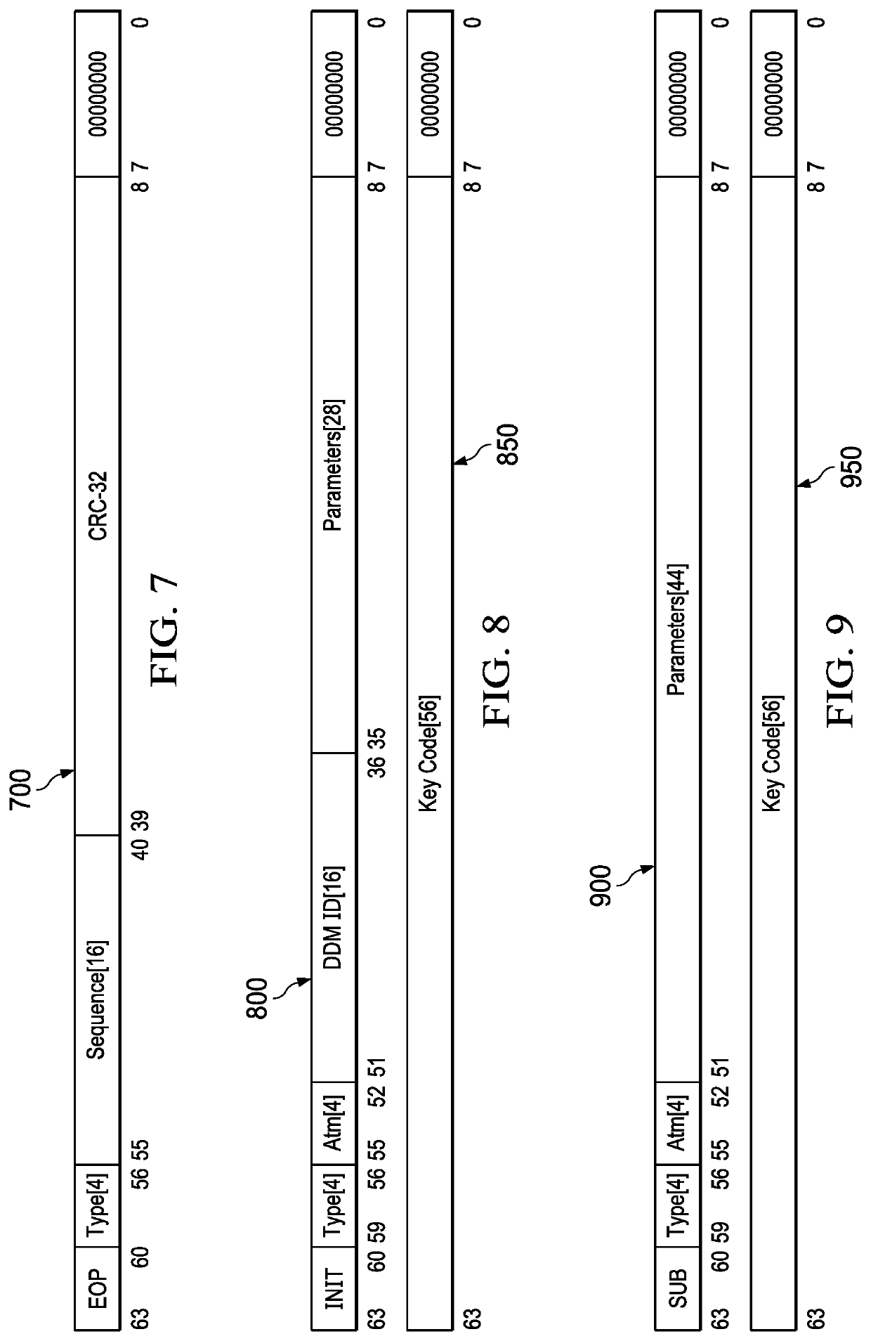
[0030]Embodiments presented in the present disclosure and the various features and advantageous details thereof are explained more fully with reference to the nonlimiting embodiments that are illustrated in the accompanying drawings and detailed in the following description. Descriptions of well-known techniques, components and equipment are omitted so as not to unnecessarily obscure the embodiments of the present disclosure in detail. It should be understood, however, that the detailed description and the specific examples are given by way of illustration only and not by way of limitation. Various substitutions, modifications, additions and / or rearrangements within the scope of the underlying inventive concept will become apparent to those skilled in the art from this disclosure.

[0031]The disclosure of this application is technically related to co-pending U.S. application Ser. No. 15 / 997,573, filed Jun. 4, 2018, co-pending PCT / US2019 / 031052, filed May 7, 2019, co-pending U.S. appli...


PUM


Abstract

Operating a computer network uses a routing and control protocol, the computer network having an interconnect fabric including routing and control distribution devices and fabric interface devices, each of the routing and control distribution devices and each of the fabric interface devices having a state machine having an input processing unit having parallel input buffers, an output processing unit having parallel output buffers and an arbiter; operating the state machine based on a set of instructions and a table located at the state machine; transferring data from the input processing unit to the output processing unit; choosing a highest priority currently flit occupied parallel input buffer located in the input processing unit for data transmission on a highest priority currently flit occupied channel; and; interrupting the highest currently flit occupied priority channel when one of the parallel input buffers is detected to contain a superseding even higher priority flit.

Description

CROSS REFERENCE TO RELATED APPLICATION[0001]This application claims the benefit of U.S. Provisional Application No. 62 / 687,785 filed on Jun. 20, 2018. This application claims the benefit of PCT / US2019 / 031052 filed on May 7, 2019, which claims priority to application Ser. No. 15 / 997,573, filed on Jun. 4, 2018. Each of the patent applications identified above is incorporated herein by reference in its entirety to provide continuity of disclosure.FIELD OF THE INVENTION[0002]The field of the invention includes parallel processors, sometimes called many-core. An example is a conventional parallel processor that splits the execution of a program among multiple processors.BACKGROUND OF THE INVENTION[0003]A problem with this parallel processing has been that the multiple processors need to be able to seamlessly communicate data and control signals. One unsatisfactory approach is a bus-based interconnect. For example, U.S. Pat. No. 7,376,295 to Lee, et al. describes opto-electronic processor...

Claims


Application Information

Patent Timeline
IPC IPC(8): H04L12/863H04L12/44
CPCH04L47/50H04L12/44H04L12/2803H04L49/201
Inventor DRESS, WILLIAM B.
Owner LIGHTFLEET CORP
Why Eureka
Eureka Blog
Learn More