

Communication system, communication terminal device, and base station device
- Summary
- Abstract
- Description
- Claims
- Application Information
AI Technical Summary
Benefits of technology
Problems solved by technology
Method used
Image

Examples
first embodiment
The First Embodiment
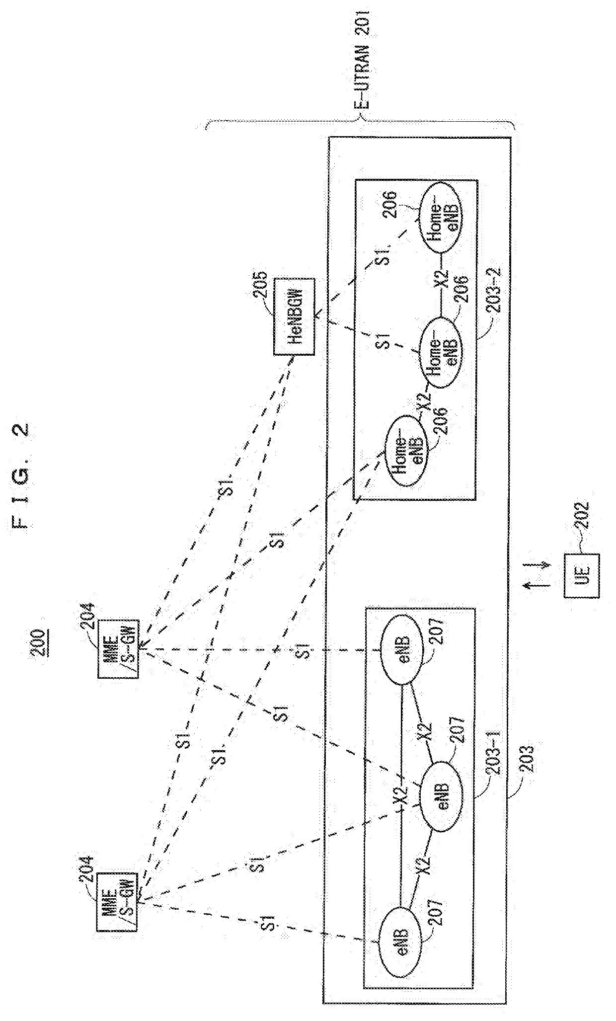
[0134]FIG. 2 is a block diagram showing an overall configuration of an LTE communication system 200 which is under discussion of 3GPP. FIG. 2 is described here. A radio access network is referred to as an evolved universal terrestrial radio access network (E-UTRAN) 201. A user equipment device (hereinafter, referred to as a “user equipment (UE)”) 202 that is a communication terminal device is capable of radio communication with a base station device (hereinafter, referred to as a “base station (E-UTRAN Node B: eNB)”) 203 and transmits and receives signals through radio communication.
[0135]Here, the “communication terminal device” covers not only a user equipment device such as a mobile phone terminal device, but also an unmovable device such as a sensor. In the following description, the “communication terminal device” may be simply referred to as a “communication terminal”.
[0136]The E-UTRAN is composed of one or a plurality of base stations 203, provided that a ...
second embodiment
The Second Embodiment
[0322]The MC (including the DC) is used as another method of the packet duplication described in the first embodiment (see Non-Patent Document 9 (3GPP TR38.804 V14.0.0)).
[0323]However, none discloses switching between the packet duplication with the CA and the packet duplication with the DC. Thus, for example, when the UE that has set the packet duplication with the CA to activation moves to a cell edge, the UE has problems of failing to switch to the packet duplication with the DC, thus failing to ensure the reliability of communication.
[0324]The second embodiment discloses a method for solving such problems.
[0325]The base station and the UE can mutually switch between the packet duplication with the CA and the packet duplication with the DC.
[0326]The base station and the UE may switch between the bearer configurations. The patterns described in Non-Patent Document 22 (R2-1704001) may be used for switching between the bearer configurations. The base station and...
third embodiment
The Third Embodiment
[0402]When the packet duplication is deactivated, clearing data in the RLC layer has been proposed (see Non-Patent Document 20 (R2-1704836)). It has been proposed that in the downlink packet duplication, the base station does not control activation / deactivation of the UE (see Non-Patent Document 21 (R2-1702753)).
[0403]In the RLC-AM, the RLC entities in the transmitter and the receiver are integrated (see Non-Patent Document 17 (TS36.322 v14.0.0)).
[0404]However, in the packet duplication using the RLC-AM, for example, the packet duplication in the SRBs, deactivation of the uplink packet duplication causes a problem of clearing a buffer of the RLC layer in the downlink packet duplication.
[0405]The third embodiment discloses a method for solving such a problem.
[0406]The UE clears only the buffer at the transmitter in the RLC-AM. The base station clears only the buffer at the transmitter in the RLC-AM. The UE and / or the base station may clear the buffer upon deactiva...
PUM
 Abstract
Description
Claims
Application Information