Additive manufacturing including compensation modeling methodology with shape transformation

a compensation modeling and shape transformation technology, applied in the field of product manufacturing, can solve the problems of significant distortion and residual stress of additively manufactured components

Active Publication Date: 2019-12-12
HAMILTON SUNDSTRAND CORP
View PDF0 Cites 4 Cited by
  • Summary
  • Abstract
  • Description
  • Claims
  • Application Information

AI Technical Summary

Problems solved by technology

Depending on process parameters and additive manufacturing process types, additively manufactured components demonstrate significant amount of distortion and residual stress.
The current proce

Method used


Image

  • Additive manufacturing including compensation modeling methodology with shape transformation
  • Additive manufacturing including compensation modeling methodology with shape transformation
  • Additive manufacturing including compensation modeling methodology with shape transformation

Examples


Embodiment Construction

[0016]A detailed description of one or more embodiments of the disclosed apparatus and method are presented herein by way of exemplification and not limitation with reference to the Figures.

[0017]The term “about” is intended to include the degree of error associated with measurement of the particular quantity based upon the equipment available at the time of filing the application. For example, “about” can include a range of ±8% or 5%, or 2% of a given value.

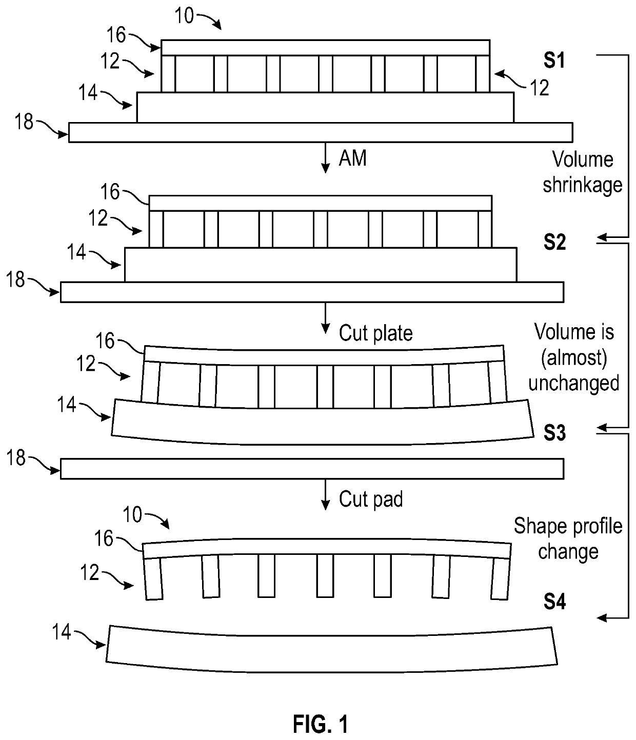
[0018]AM parts are susceptible to “springback” during the fabrication process. For instance, the part can realize compression and / or expansion states (e.g., bending) during fabrication. This springback phenomenon is typically caused by the part' inherent desire to return to its nominal profile following removal of the compression and / or expansion force. The resulting springback, however, causes distortion of the part along with residual stresses on one or more regions and / or connection points of the part.

[0019]In addition, AM pa...


PUM

PropertyMeasurementUnit
Volumeaaaaaaaaaa
Shapeaaaaaaaaaa
Deformation enthalpyaaaaaaaaaa

Abstract

An additive manufacturing (AM) system includes a process distortion compensation computing system and an AM peripheral device. The process distortion compensation computing system determines a digital nominal model that represents a physical target object excluding a distortion, and a digital distortion model that represents the physical target object including at least one distortion. The AM peripheral device forms a three-dimensional (3D) physical object based on a digital compensation model. The process distortion compensation computing system also determines a digital skeletal model indicating a predicted change in at least one of the shape and volume of the nominal model, and generates the digital compensation model based on the skeletal model that compensates for the at least one distortion.

Description

CROSS-REFERENCE TO RELATED APPLICATIONS[0001]This application claims the benefit of Chinese Application No. 201810578857.X filed Jun. 6, 2018, which is incorporated herein by reference in its entirety.BACKGROUND[0002]The disclosure relates generally to product manufacturing, and more particularly, to additive manufacturing processes.[0003]Additive manufacturing includes building two-dimensional layers (or slices), on a layer by layer basis to manufacture three-dimensional components. For laser powder bed diffusion and laser directed energy deposition processes Each layer is generally very thin (for example between 20 to 100 microns) and many layers are formed in a sequence with the two-dimensional (2D) shape varying on each layer to provide the desired final three-dimensional (3D) profile. On the other hand wire based additive manufacturing processes can deposit layers with mm height. In contrast to traditional “subtractive” manufacturing processes where material is removed to form ...

Claims


Application Information

Patent Timeline
IPC IPC(8): G06F17/50G06T17/20B29C64/393
CPCG06F17/5018G06T17/20G06T2210/44G06T2210/56G06F2217/12B33Y50/02B29C64/393G06Q50/04G06T17/00G06T19/20G06T2219/2021G06F30/23G06F2119/18
Inventor CHEN, YANZHIZHANG, QINGQINGEL-WARDANY, TAHANY IBRAHIMACHARYA, RANADIPFENNESSY, COLETTE OPSAHLTREDWAY, WILLIAM K.
Owner HAMILTON SUNDSTRAND CORP
Why Eureka
Try Eureka