A Carriage Decking Device

a technology of carriages and decking, applied in the field of mechanical technology, can solve the problems of low utilization rate of storage cavities, inability to adjust storage cavity space, damage to goods, etc., and achieve the effects of improving stability at the time of adjustment, increasing deck area, and convenient adjustmen

Active Publication Date: 2019-12-19
ZHEJIANG TOPSUN LOGISTIC CONTROL CO LTD
View PDF0 Cites 2 Cited by
  • Summary
  • Abstract
  • Description
  • Claims
  • Application Information

AI Technical Summary

Benefits of technology

[0024]In the carriage decking device, the upper and lower sides of the mounting cavity are provided with a semi-circular positioning slot respectively, and both the stop pins are located in the positioning slot respectively. By mounting the two stop pins on the two semi-circular positioning slots, stability at the time of adjustment can be improved, ensuring that the stop pins will not traverse to the other directions apart from axial movement.
[0025]In the carriage decking device, one end portion of the rod is provided with a hook folded to one side. By folding one end portion of the rod into a hook, users can carr

Problems solved by technology

However, the turbulence of vehicle during transport process is likely to cause damage to the goods.
However, the shelf itself requires to occupy a certain amount of space in the carriage, and the partition is being fastened to the shelf, thus the storage cavity space cannot be adjusted, which is only applicable to specific goods.
If the size of goods is small, the utilization

Method used


Image

  • A Carriage Decking Device
  • A Carriage Decking Device
  • A Carriage Decking Device

Examples


first embodiment

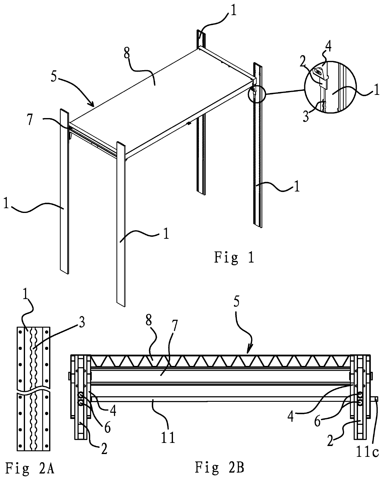
[0039]As shown in FIGS. 1, 2A and 2B, a carriage decking device comprises four deck maneuver rails 1 arranged in pairs and opposite one another, and connectors 2, connected at the deck maneuver rails 1, and which are capable of sliding up and down along the deck maneuver rails 1. A certain number of positioning holes 3 are axially distributed on the deck maneuver rails 1. As shown in FIGS. 5 and 9, a projecting slider 2b is provided on the internal side of connector 2. Slider 2b is located in the deck maneuver rail 1. Both upper and lower ends of slider 2b have a notch 2b1. A plastic block 2b2 of matching shape with notch 2b1 is being connected with notch 2b1. Both the connector 2 and deck maneuver rail 1 are made of aluminum extruded sections. When the slider 2b of connector 2 slides on deck maneuver rail 1, a large frictional force is formed, and it gets stuck easily. Therefore, a plastic block 2b2 is disposed on upper and lower ends of slider 2b to reduce the frictional force dur...

second embodiment

[0048]The structure and principles of this embodiment is basically the same as First Embodiment, except the following difference:

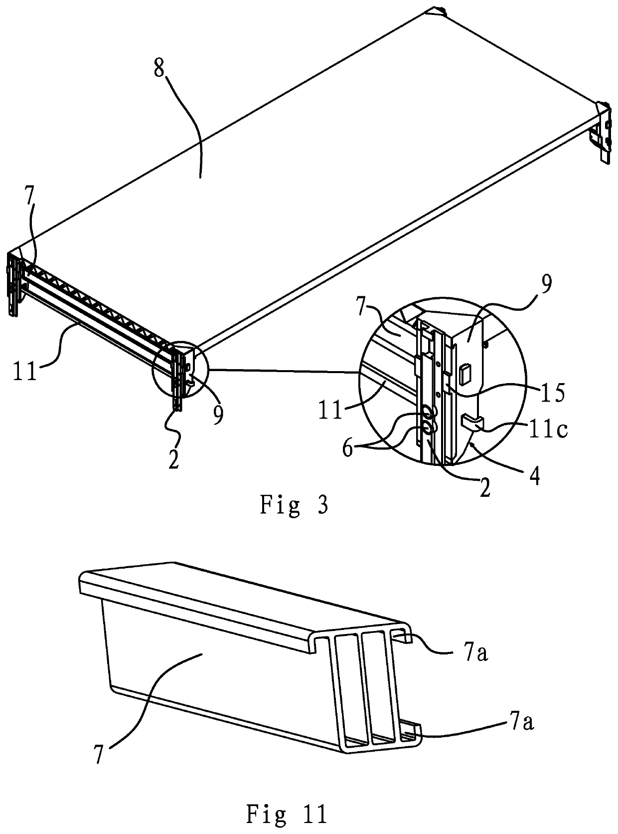
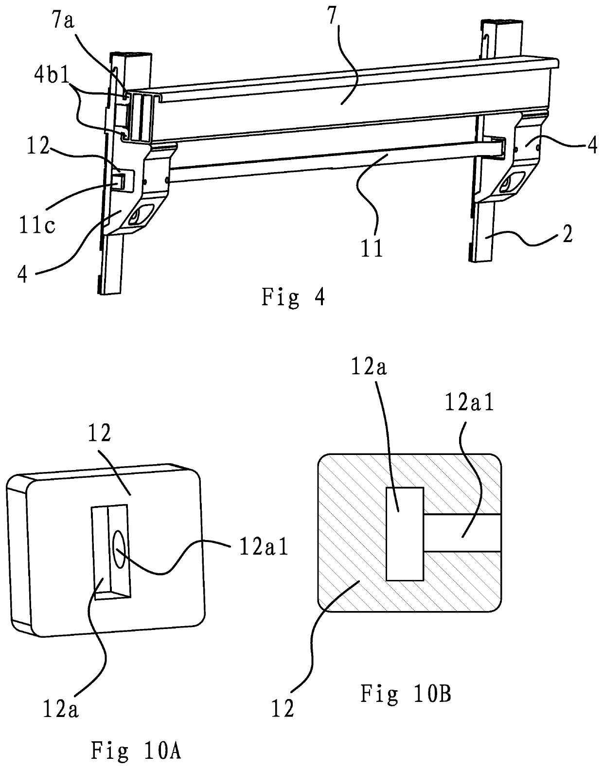
[0049]In this embodiment, positioning steps 4b are provided on external sides of yokes 4. The partition 5 comprises a beam 7 connecting in-between the positioning steps 4b on two neighboring yokes 4 and several parallel disposed supporting joists. Both ends of supporting joists are lap-joined with the beam 7 in-between various neighboring yokes 4 respectively. The side of each of the neighboring two yokes 4 near the end edge of beam 7 is connected with a sealing plate 9 respectively. Similar effect of increasing decking area could be achieved by using a plurality number of supporting joists. Meantime, when compared with platform 8, a certain interval can be set up between various supporting joists, hence meeting the need of decking as well as saving material cost.

third embodiment

[0050]The structure and principles of this embodiment is basically the same as First Embodiment, except the following difference:

[0051]In this embodiment, a connecting board is disposed in-between the mounting cavities 4a of two neighboring yokes 4. The stop pins 6 are secured at end portion of connecting board. A limit spring is disposed between the connecting board and mounting cavity 4a. The clutch comprises a connecting rod disposed under platform 8 and steel wire rope connected between the connecting rod and connecting board. Both ends of limit spring are being placed against the connecting board and mounting cavity 4a respectively. The steel wire rope passing through the rotating rod, and both ends of steel wire rope are connected on the connecting board in-between various two neighboring yokes 4 respectively. Both ends of limit spring are placed against the connecting board and positioning seat respectively. Under normal conditions, stop pins 6 extended out from connecting ho...


PUM


Abstract

The carriage decking device comprises four deck maneuver rails arranged in pairs and opposite one another, and connectors, connected at the deck maneuver rails, and which are capable of sliding up and down along the deck maneuver rails. A certain number of positioning holes are axially distributed on the deck maneuver rails. Yokes are connected on external sides of each connector, and partitions are fastened between the yokes. A depressed mounting cavity is provided on the internal side of each yoke, and a stop pin is provided inside the mounting cavity. A connecting hole that aligns with the stop pin is provided on each connector, and the stop pin extends into the connecting hole. A clutch that enables the stop pins in the mounting cavities to connect with the positioning holes of corresponding deck maneuver rails or to detach from the positioning holes simultaneously is provided between two neighboring yokes. and easily adjustable heights.

Description

BACKGROUND OF THE INVENTIONField of Invention[0001]The present invention pertains to the technical field of mechanical technology, and particularly to a carriage decking device.Related Art[0002]In order to save transportation costs, and improve transport capacity of goods, a large number of goods will be stacked in the carriage during transportation. However, the turbulence of vehicle during transport process is likely to cause damage to the goods. Some people have thought of placing a semi-enclosed shelve in the carriage, with a partition fastened on the shelf, so the shelf is separated by a partition into a number of vertically adjacent storage cavities, and the goods are placed in each cavity. However, the shelf itself requires to occupy a certain amount of space in the carriage, and the partition is being fastened to the shelf, thus the storage cavity space cannot be adjusted, which is only applicable to specific goods. If the size of goods is small, the utilization rate of stor...

Claims


Application Information

Patent Timeline
IPC IPC(8): B65D90/00B65D88/12
CPCB65D90/0073B65D2590/0041B65D88/121B65D2590/005A47B57/10A47B57/265A47B57/34A47B57/545
Inventor NIU, SHENGLIANG
Owner ZHEJIANG TOPSUN LOGISTIC CONTROL CO LTD
Why Eureka
Try Eureka