Joint optimization of antenna spacing and target angle estimation in a radar system

a radar system and target angle technology, applied in the direction of antennas, instruments, movable bodies, etc., can solve the problems of resolving and accurately estimating the angle of arrival, and the difficulty of analytical determination of the dependence of the angle of arrival estimation on the spacing of the antenna

Inactive Publication Date: 2019-12-19
GM GLOBAL TECH OPERATIONS LLC
View PDF3 Cites 5 Cited by
  • Summary
  • Abstract
  • Description
  • Claims
  • Application Information

AI Technical Summary

Problems solved by technology

When multiple close-in targets appear at the same range and velocity from the radar system, resolving and accurately estimating their angles of arrival is a known challenge in radar applications.
An analytical determination of the dependence of angle of arrival estimation on the spacing of antennas is difficult.

Method used


Image

  • Joint optimization of antenna spacing and target angle estimation in a radar system
  • Joint optimization of antenna spacing and target angle estimation in a radar system
  • Joint optimization of antenna spacing and target angle estimation in a radar system

Examples


Embodiment Construction

[0028]The following description is merely exemplary in nature and is not intended to limit the present disclosure, its application or uses. It should be understood that throughout the drawings, corresponding reference numerals indicate like or corresponding parts and features.

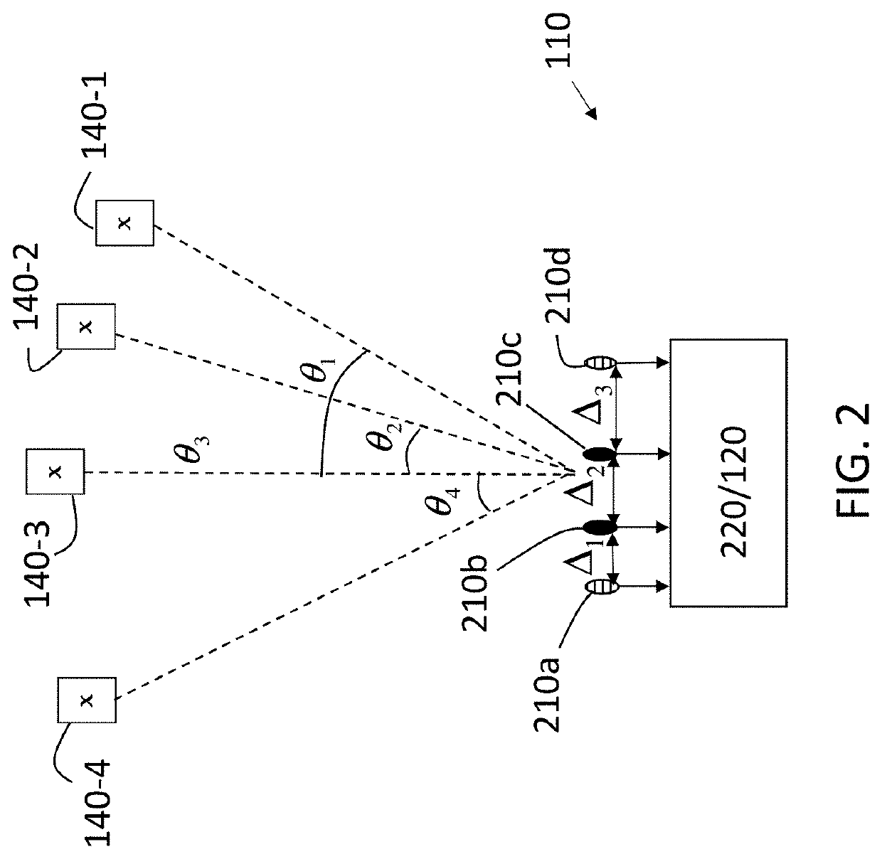
[0029]As previously noted, a radar system with multiple antennas must distinguish the relative angles of multiple targets that appear at the same range. While target angle of arrival estimation is dependent on the antenna array configuration (i.e., spacing among antennas), this dependency is difficult to determine analytically. Embodiments of the systems and methods detailed herein relate to joint optimization of antenna spacing and target angle estimation in a radar system. A machine learning approach is applied iteratively to a number of angles of arrival to converge on an antenna spacing configuration and on parameters for angle of arrival estimation.

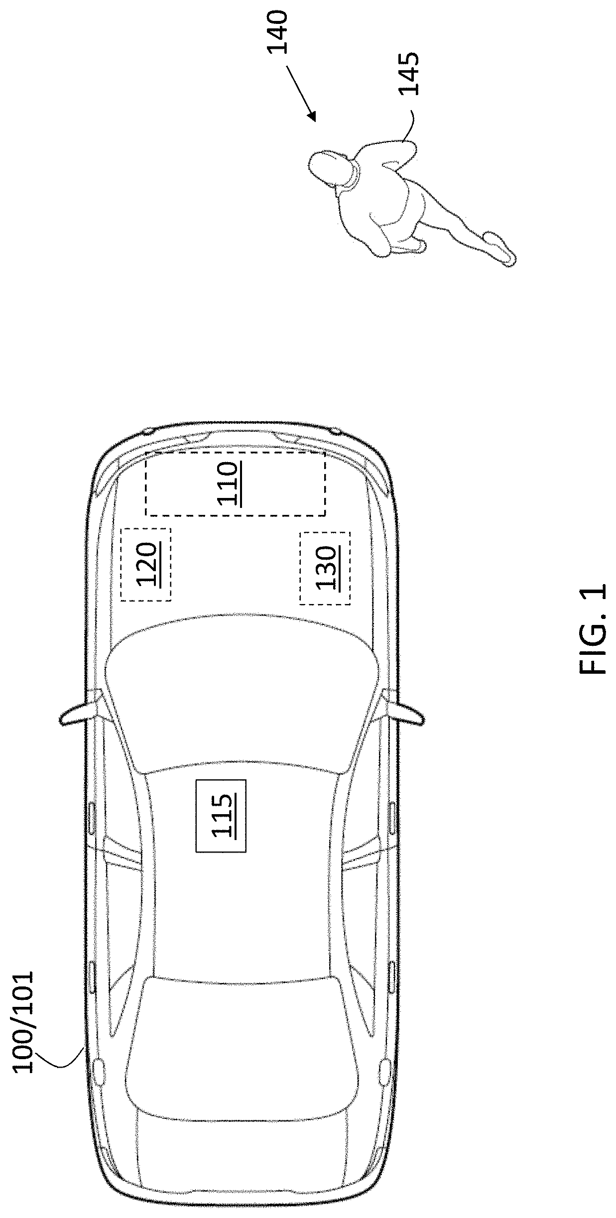
[0030]In accordance with an exemplary embodiment, FIG. 1 i...


PUM


Abstract

A radar system and a method to configure the radar system involve one or more transmit antennas to transmit a radio frequency signal, and one or more receive antennas to receive reflected energy based on the radio frequency signal transmitted by the one or more transmit antennas. The one or more transmit antennas and the one or more receive antennas are arranged in an array. A processor jointly determines a spacing among the one or more transmit antennas and the one or more receive antennas arranged in the array and a mapping between data obtained by the one or more receive antennas and an angle of arrival of one or more targets detected in the data. Joint determination refers to both determination of the spacing being in consideration of the mapping and determination of the mapping being in consideration of the spacing.

Description

INTRODUCTION[0001]The subject disclosure relates to joint optimization of antenna spacing and target angle estimation in a radar system.[0002]Vehicles (e.g., automobiles, trucks, construction equipment, farm equipment, automated manufacturing equipment) increasingly use sensors to detect objects in their vicinity. The detection may be used to augment or automate vehicle operation. Exemplary sensors include cameras, light detection and ranging (lidar) systems, radio detection and ranging (radar) systems. A radar system may include multiple antennas. When multiple close-in targets appear at the same range and velocity from the radar system, resolving and accurately estimating their angles of arrival is a known challenge in radar applications. In conventional radar systems with multiple antennas, the spacing between antennas is determined such that a standard beamforming algorithm will provide a narrow main lobe (i.e., maximum amplitude response) at the target angle and low sidelobes o...

Claims


Application Information

Patent Timeline
Patent Type & Authority Applications(United States)
IPC IPC(8): G01S7/40H01Q1/32G01S13/93G01S13/06G01S7/41G01S13/931
CPCH01Q21/00G01S7/417G01S7/4021G01S13/931H01Q1/3233G01S13/06G01S7/40G01S13/42
Inventor BIALER, ODEDGARNETT, NOALEVI, DAN
Owner GM GLOBAL TECH OPERATIONS LLC
Why Eureka
Try Eureka