
Instantaneous control device for a date display of a timepiece

Active Publication Date: 2019-12-19
DE LA MFG DHORLOGERIE AUDEMARS PIGUET & CIE
View PDF0 Cites 0 Cited by
  • Summary
  • Abstract
  • Description
  • Claims
  • Application Information

AI Technical Summary

Benefits of technology

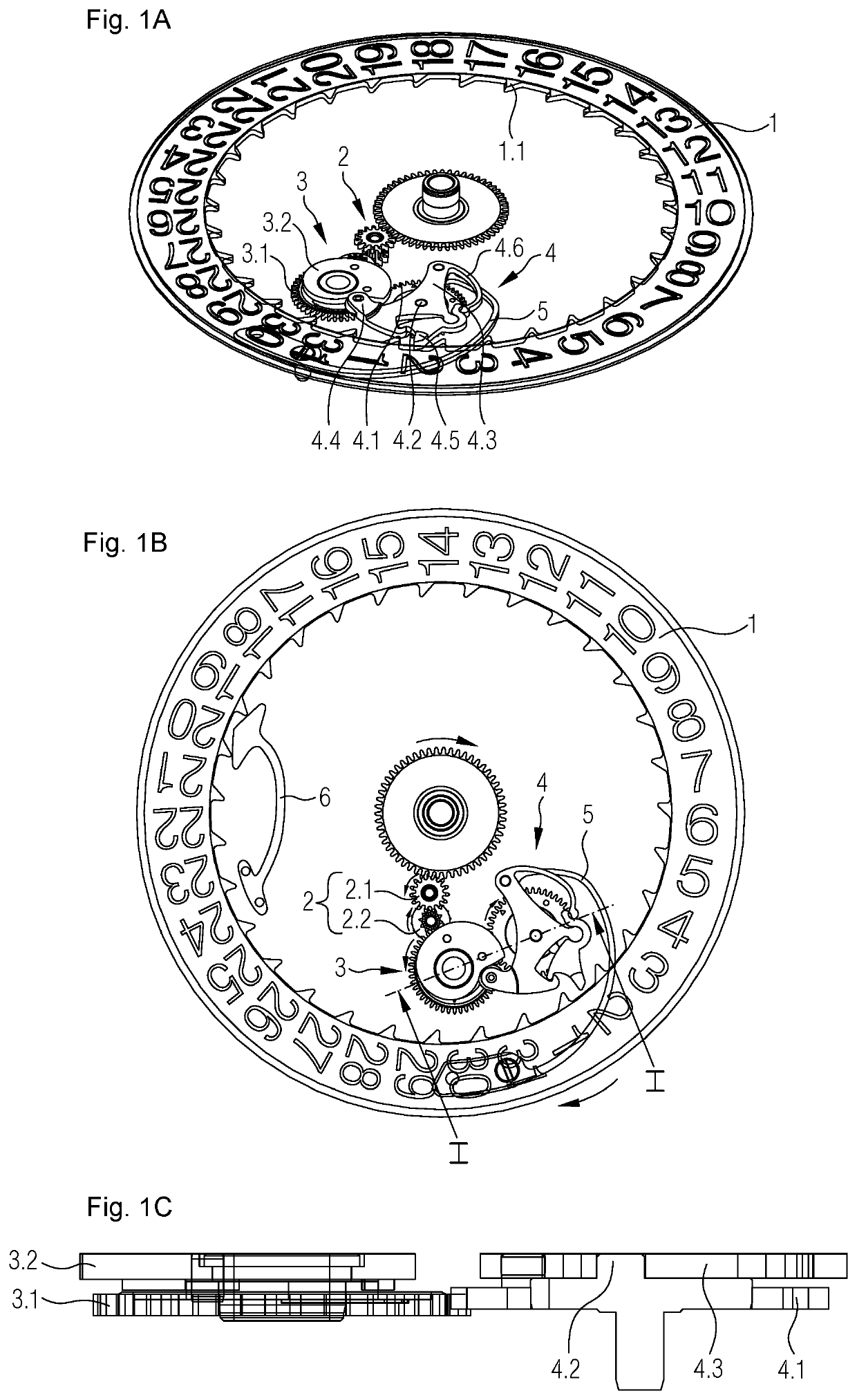
The present invention provides an improved instantaneous date control device for horological date displays that overcomes the disadvantages of known devices. The device allows for effective protection of the date disc against a double jump, allows for manual correction of the time and / or of the date, provides a possibility of rapid correction of the date, without any restriction in time ranges, and ensures a reliable operation. The device is designed to minimize the capture of torque from the horological movement of the respective timepiece, and the trajectory of the moving parts during operation of the device is optimized. The device is relatively low-bulk and modular construction, suitable for extra-thin movements, and is reliable and safe. The unlocking and driving yoke is pivotably mounted about a pivot axis on a second toothed wheel in a manner that allows for optimal trajectory of the various parts of the device. The device also allows for separation of the unlocking and driving force and the biasing force, improving ease of use.

Problems solved by technology

These displays overcome the disadvantages of date displays of the calendar-dragging change type which are normally rather simple in construction, but can only execute a date change which can be fairly slow and is thus clearly perceptible to the user.
However, it does not completely overcome this problem, because a manual correction is not possible during the instantaneous change of the date.
In addition, guiding the trajectory of the driving lever of the mechanism in accordance with the document DE 10 2015 011 324 by sliding, which also occurs in the mechanism in accordance with the document DE 1 673 663, does not appear to be optimal.
Furthermore, protecting the date disc against a double jump is always a problem with these mechanisms, given that the energy necessary to carry out the instantaneous jump of the date disc is released over a very short period of time and could cause, under some circumstances, an unwanted double jump.
Similarly, the capture of torque by this type of mechanism from the horological movement of the respective timepiece is always delicate, as this capture of torque should be distributed over a maximum period of time, while allowing simultaneously for the instantaneous release of the accumulated energy, in order to minimize the influence on the chronometric performance of the horological movement.

Method used


Image

  • Instantaneous control device for a date display of a timepiece
  • Instantaneous control device for a date display of a timepiece
  • Instantaneous control device for a date display of a timepiece

Examples


first embodiment

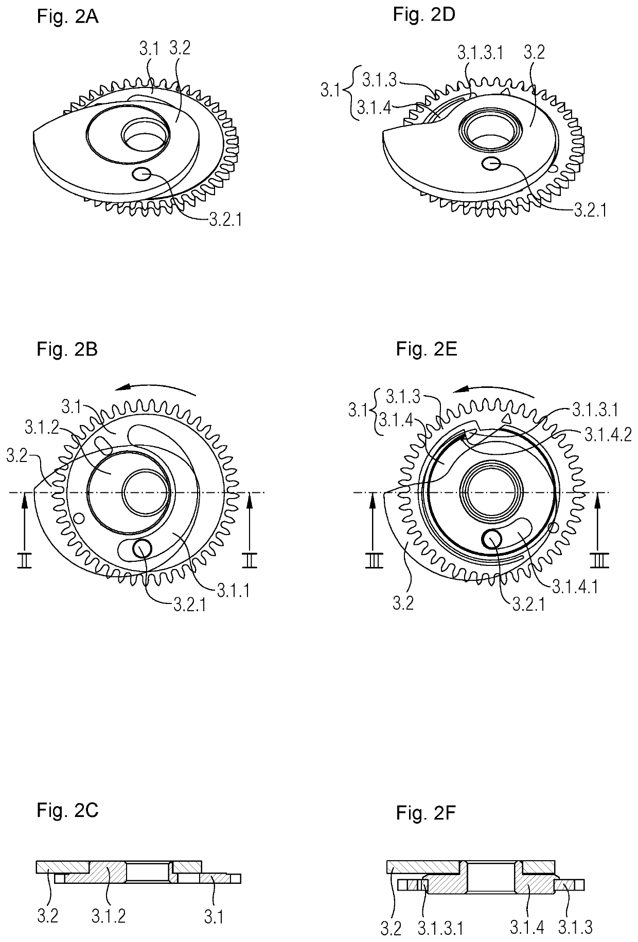
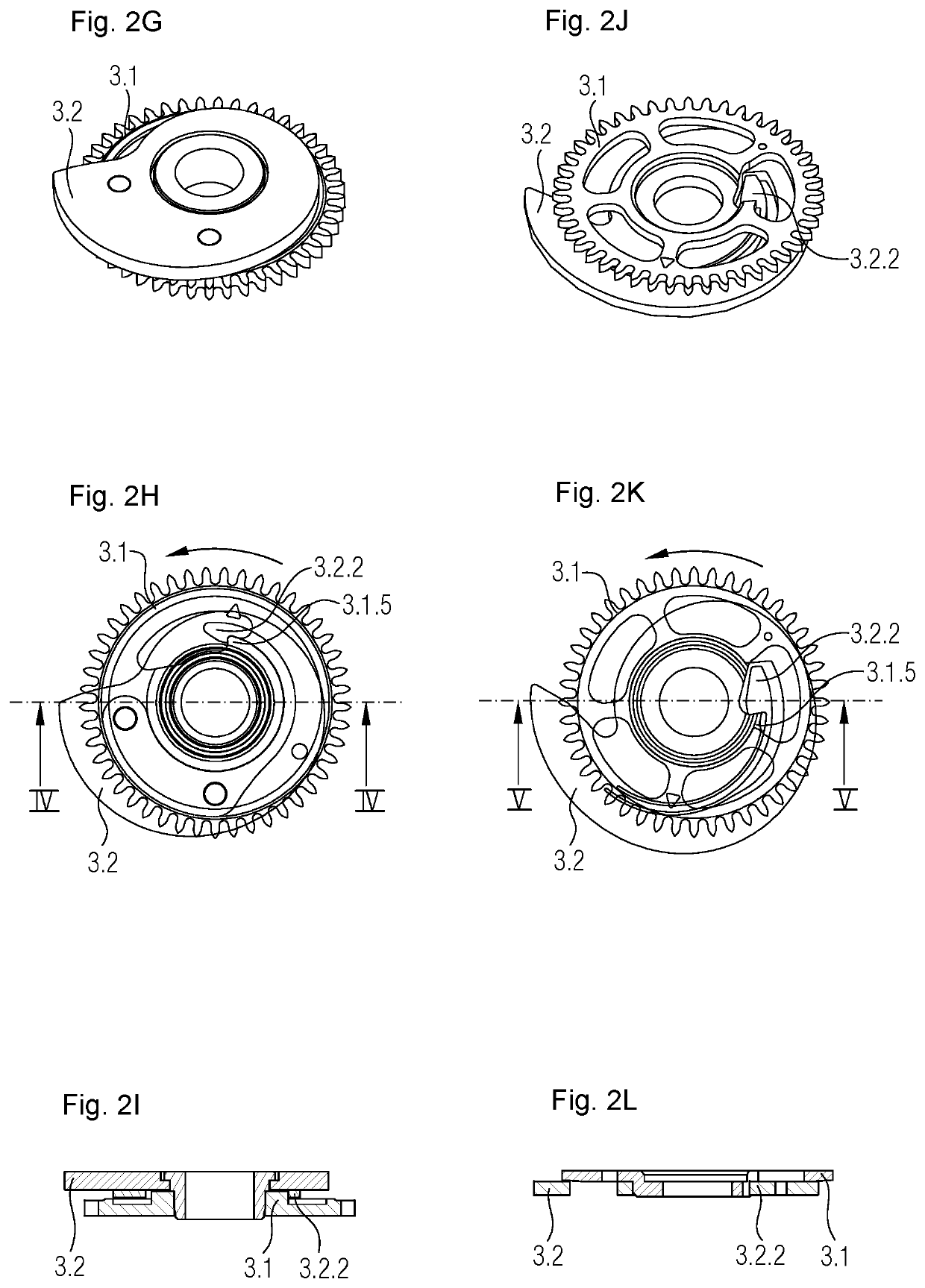
[0025]The set of FIGS. 2A to 2C, 2D to 2F, 2G to 2I and 2J to 2L represent, each time in a perspective view, a top plan view and a cross section, four different embodiments of the first mobile of an instantaneous date control device in accordance with the present invention. In the first mobile, illustrated in the set of FIGS. 2A to 2C, the cam 3.2 is mounted so as to be free to rotate over a limited angular range on said first toothed wheel 3.1 as well as temporarily coupled in rotation to said first toothed wheel 3.1 via a guide slot 3.1.1 substantially in the form of a semi-circular arc arranged on the first toothed wheel 3.1 as well as a pin 3.2.1 fixed on the cam and housed in said guide slot 3.1.1, or vice versa. In addition, said cam 3.2 is rotatably mounted on said first toothed wheel 3.1 about an axis of rotation 3.1.2 which is eccentric with respect to the axis of rotation of the first toothed wheel 3.1, said guide slot 3.1.1 substantially in the form of a semi-circular arc...

second embodiment

[0026]In the first mobile, illustrated in the set of FIGS. 2D to 2F, the cam 3.2 is freely rotatably mounted on said first toothed wheel 3.1 over a limited angular range as well as temporarily coupled in rotation to said first toothed wheel 3.1 via a guide slot 3.1.4.1 substantially in the form of a sector of a circular arc arranged on the first toothed wheel 3.1, this sector preferably having an angular extent which is located in the range from 25° to 65°, as well as a pin 3.2.1 fixed on the cam and housed in said guide slot 3.1.4.1, or vice versa. In addition, the first toothed wheel 3.1 is separated into two parts, namely into a ring 3.1.3 of the first toothed wheel driven in the anticlockwise direction by said gear train 2 and into a disc 3.1.4 of the first toothed wheel. The disc 3.1.4 comprises said guide slot 3.1.4.1 and is housed inside the ring 3.1.3 so as to be freely rotatable, but kinematically linked to the ring 3.1.3 via a unidirectional clutch means arranged on these ...

third embodiment

[0027]In the first mobile, illustrated in the set of FIGS. 2G to 2I and also in FIGS. 1A to 1C, the cam 3.2 is mounted on said first toothed wheel 3.1 so as to be freely rotatable in a single direction of rotation and also is temporarily coupled in rotation to said first toothed wheel 3.1 via a unidirectional clutch means 3.1.5, 3.2.2 arranged between the first toothed wheel 3.1 and the cam 3.2. In this regard, the first toothed wheel 3.1 comprises a driving shoulder 3.1.5 of the unidirectional clutch means and the cam 3.2 comprises a corresponding hook 3.2.2 of the unidirectional clutch means in a manner such that driving the first toothed wheel 3.1 in the anticlockwise direction also causes the cam 3.2 to be driven as soon as the driving shoulder 3.1.5 of the first toothed wheel 3.1 comes into contact with the hook 3.2.2 of the cam 3.2, while driving the first toothed wheel 3.1 in the clockwise direction causes a disengagement of the unidirectional clutch means in a manner such th...


PUM


Abstract

An instantaneous date control device for a timepiece, in particular for a mechanical wristwatch, comprising: a date disc, a gear train forming a kinematic linkage between the control device and a horological movement of said timepiece, a first mobile comprising a first toothed wheel driven at a speed of one turn per day and a cam mounted freely rotatably, over a limited angular range and / or in a single direction of rotation, as well as temporarily coupled in rotation to said first toothed wheel, a second mobile comprising a second toothed wheel driven at a speed of one turn per day, an unlocking and driving yoke carrying a feeler bearing on said cam and a driving finger which can mesh with teeth located on the date disc, an unlocking and driving spring, and a retaining means allowing to secure the angular position of the date disc between two instantaneous jumps.

Description

RELATED APPLICATION[0001]The present application claims priority to European Patent Application No. 18178458.8, filed Jun. 19, 2018, the disclosure of which is hereby incorporated by reference herein in its entirety.FIELD OF THE INVENTION[0002]The present invention relates to a device for the instantaneous control of the date for a date display of a timepiece, in particular for a date display of a mechanical wristwatch, and to a horological movement, respectively to a timepiece comprising said instantaneous date control device.BACKGROUND[0003]In general, date displays of the instantaneous change type are known in horology. These displays overcome the disadvantages of date displays of the calendar-dragging change type which are normally rather simple in construction, but can only execute a date change which can be fairly slow and is thus clearly perceptible to the user. Amongst others, this is noticeable by the fact that the displayed date is no longer centered in the date window for...

Claims


Application Information

Patent Timeline
IPC IPC(8): G04B19/253
CPCG04B19/25353G04B19/25386G04B19/253G04B19/25373
Inventor REY-MERMET, GILLESGOY, NICOLAS
Owner DE LA MFG DHORLOGERIE AUDEMARS PIGUET & CIE
Learn More