Slide Valve for Controlling Fluid Flow
- Summary
- Abstract
- Description
- Claims
- Application Information
AI Technical Summary
Benefits of technology
Problems solved by technology
Method used
Image

Examples
first embodiment
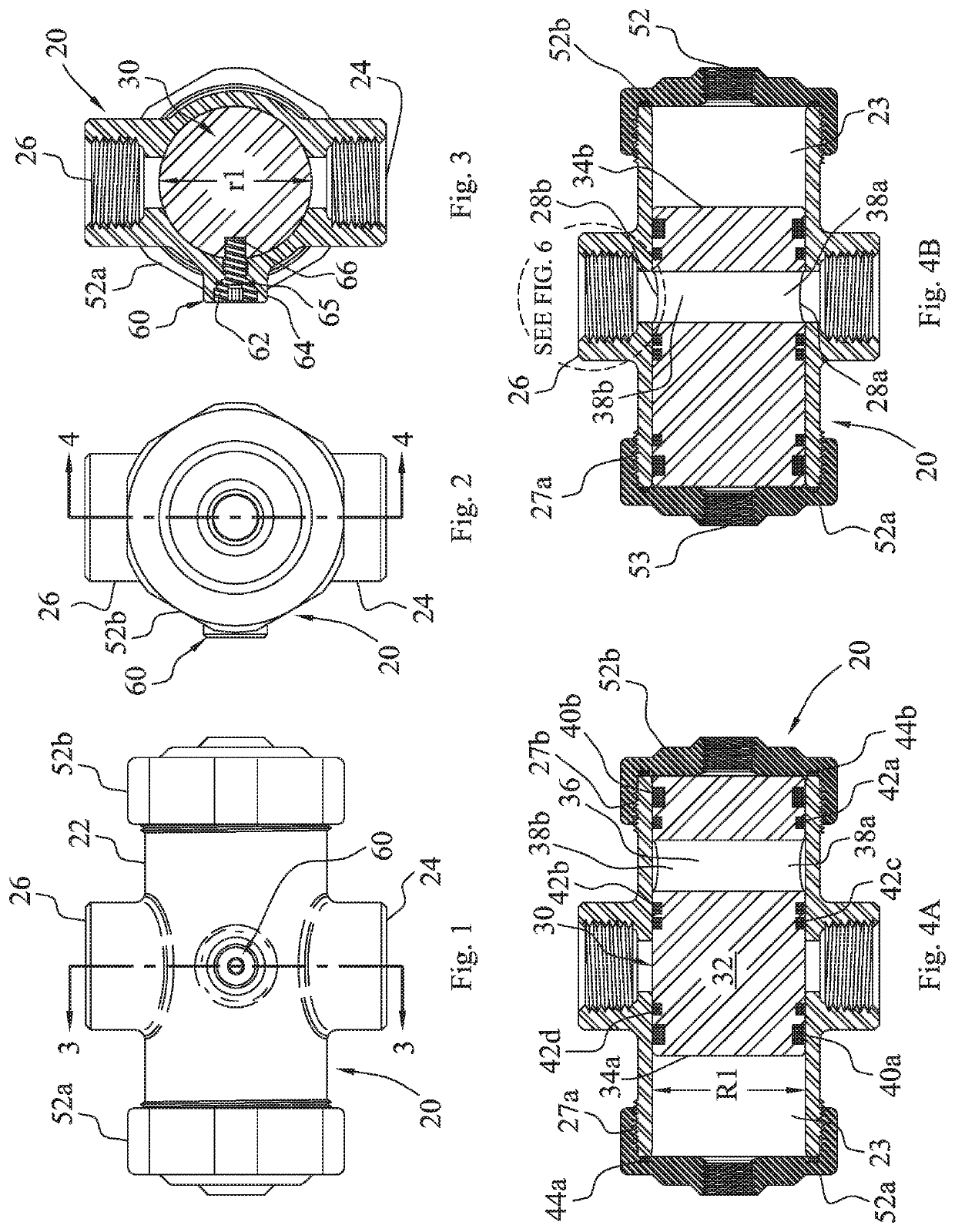
[0019]the slide valve of the present invention is depicted in FIGS. 1-4B generally at 20. Slide valve 20 comprises a housing 22 having an elongated cylindrical chamber 23 extending in a first axial direction with a first internal radial dimension R1. Housing 22 has a first inlet passageway means 24 and a first outlet passageway means 26 extending in a second axial direction orthogonal to the first axial direction. Spool 30 has a body portion 32 extending in a third axial direction co-extensive with the first axial direction and having an external radial dimension ‘r1’ substantially equal to the first internal radial dimension of the passageway. A first circumferential seal means 40a surrounds spool 30 in groove 33a (FIG. 5A) near a first end 34a of the spool for sealing the first end in housing 22. A second circumferential seal means 40b surrounds spool 30 in groove 33b near a second end 34b for sealing the second end in housing 22.
[0020]A lateral passageway 36 extends through the b...
second embodiment
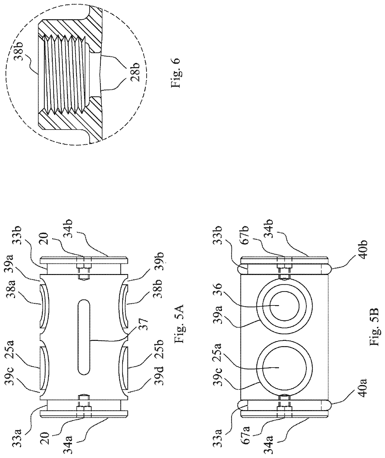
[0021]Alignment means 60 is operable between the elongated cylindrical chamber 23 and the spool 30 maintaining proper rotational alignment of the lateral passageway 36 with the first inlet passageway means 24 and the first outlet passageway means 26. Alignment means 60 comprises a screw 62 threaded into nipple 64. O-ring 65 surrounds the head of screw 62 to inhibit leakage through nipple 64. Unthreaded portion 66 of screw 62 slides in a slot 37 (best seen in FIG. 5A) preventing rotation of spool 30 within chamber 23 which would misalign lateral passageway 36 with respect to first inlet passageway means 24 and first outlet passageway means 26. A threaded capture aperture 67a can be formed in the end 34a of spool 30 as shown in the spool 30 depicted in FIGS. 5A and 5B. Similarly, a threaded aperture67b is formed in end 34b of spool 30. Threaded apertures 67a, 67b permit the end of a complementarily threaded tool (not shown) to capture the spool 30 to remove it from housing 22 to permi...
PUM
 Abstract
Description
Claims
Application Information