
Anvil plate for a surgical stapling instrument

a technology for surgical stapling and anvils, which is applied in the field of anvils for surgical stapling instruments, can solve the problems of rejected units, high cost, and high labor intensity of conventional coining process, and achieve the effect of being ready to manufactur

Inactive Publication Date: 2020-01-02
TYCO HEALTHCARE GRP LP
View PDF0 Cites 131 Cited by
  • Summary
  • Abstract
  • Description
  • Claims
  • Application Information

AI Technical Summary

Benefits of technology

The patent describes a anvil plate used in a surgical stapling instrument. The anvil plate has a unique design that makes it easy to manufacture and assemble. The outer beams of the anvil plate are positioned around the sides of the anvil support column, and there is a fixation tab on one of the outer beams that attaches to a recess in the column to secure the anvil plate in place. This feature makes it simple to use the anvil plate in a surgical setting and ensures accurate placement of the staple forming pockets. Overall, this design simplifies the manufacturing process and improves the functionality of the anvil plate in a surgery.

Problems solved by technology

The manufacture of an anvil via conventional coining processes is expensive considering the complexity of the machinery, and is also labor intensive.
In addition, assembly of the anvil within the stapling instrument often requires delicate welding applications which are highly skill dependent often resulting in rejected units and associated extra expense.

Method used


Image

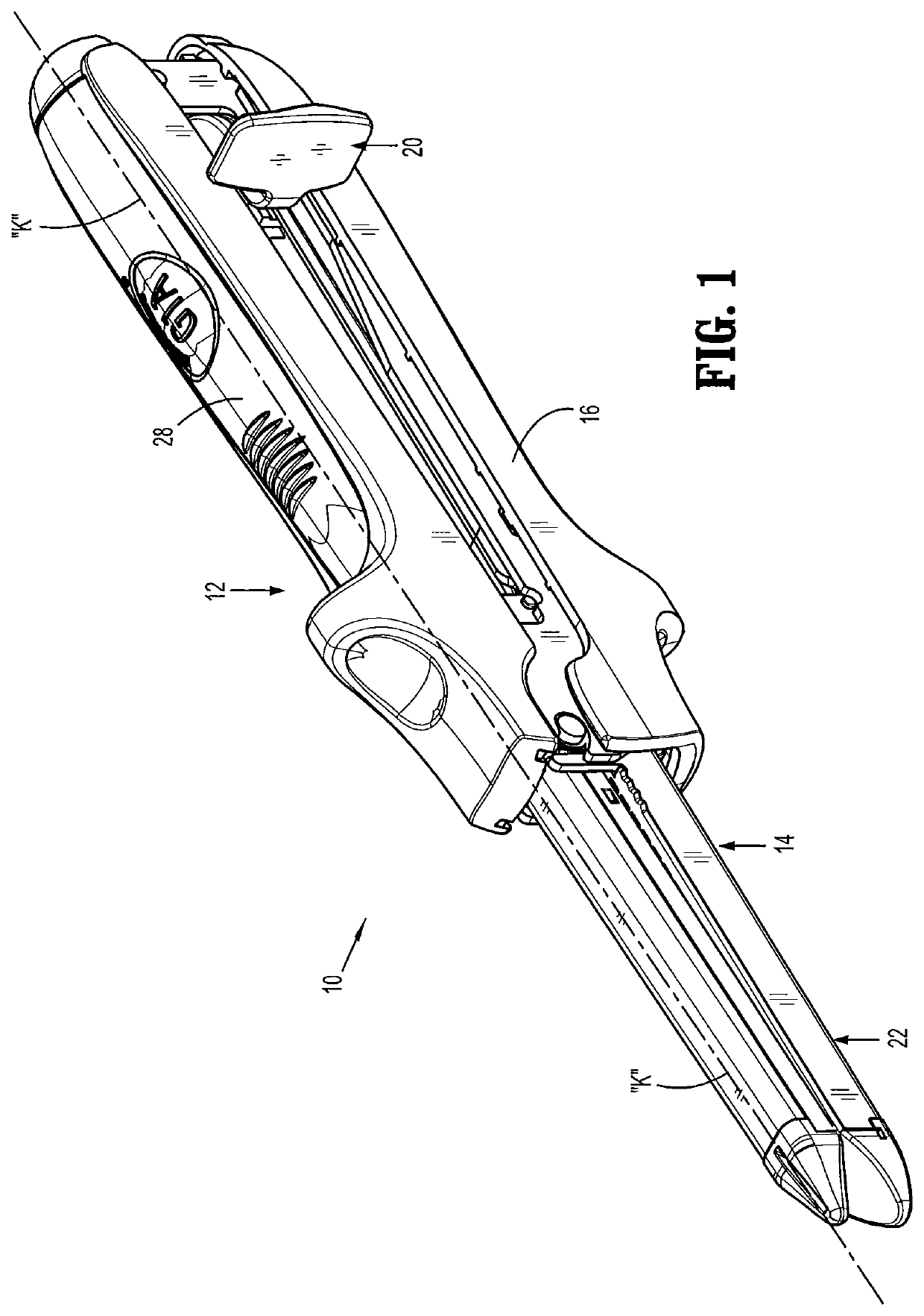
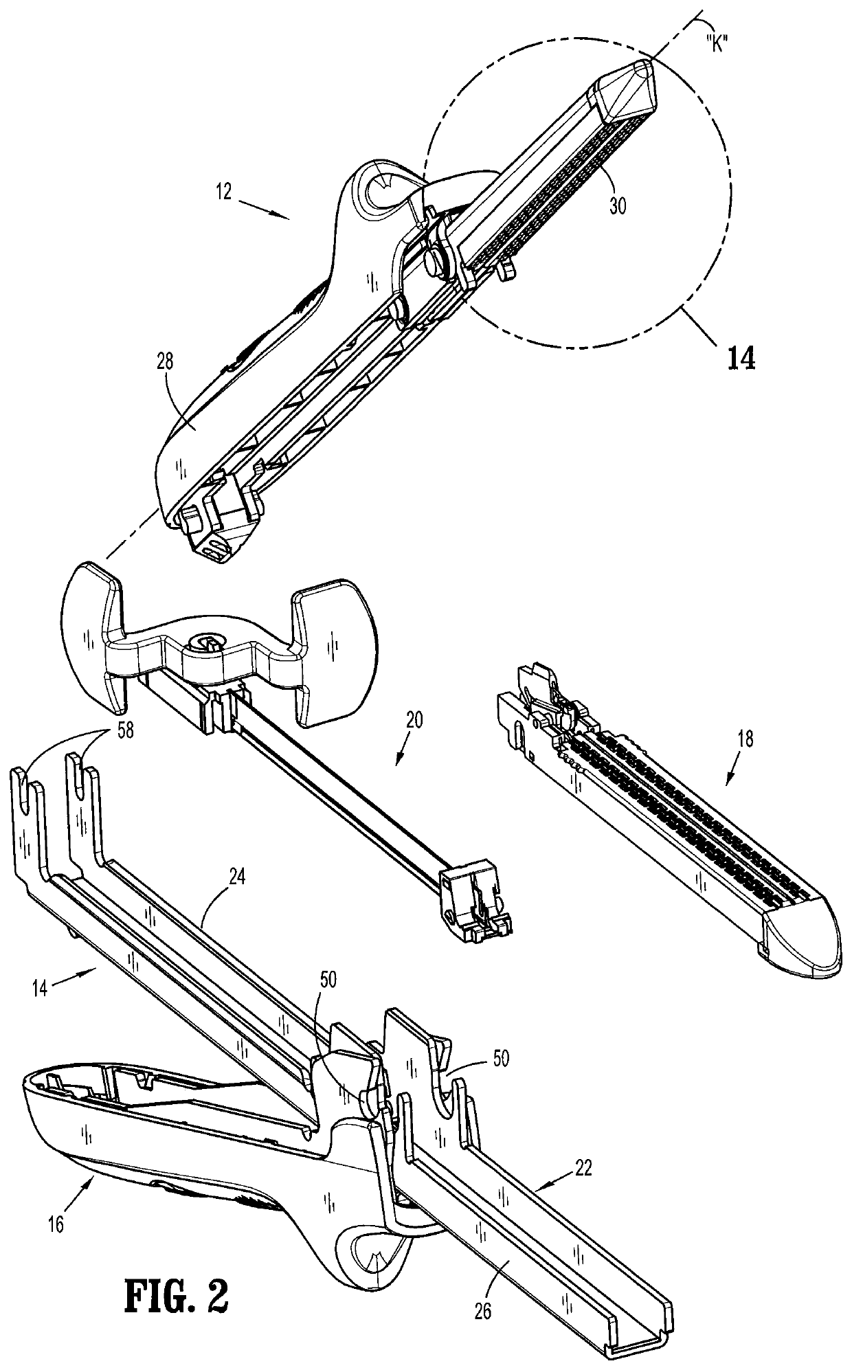
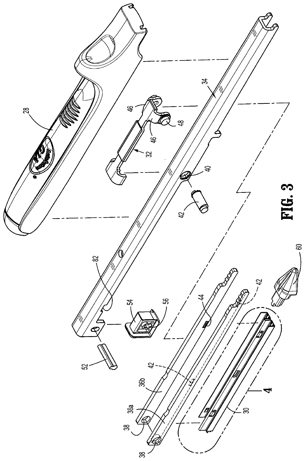
  • Anvil plate for a surgical stapling instrument
  • Anvil plate for a surgical stapling instrument
  • Anvil plate for a surgical stapling instrument

Examples


Embodiment Construction

[0024]The surgical stapling instrument and associated anvil plate of the present disclosure will now be described in detail with reference to the drawings in which like reference numerals designate identical or corresponding elements in each of the several views. In this description, the term “proximal” is used generally to refer to that portion of the device that is closer to a clinician, while the term “distal” is used generally to refer to that portion of the device that is farther from the clinician. In addition, the term clinician is used generally to refer to medical personnel including doctors, nurses, and support personnel.

[0025]The surgical stapling instrument of the present disclosure includes an anvil plate, a staple cartridge, an actuator or lever that is configured to move the anvil and the staple cartridge between a spaced position and a clamped position, and a firing mechanism for ejecting staples from the staple cartridge. The anvil plate is readily adaptable within ...


PUM


Abstract

An anvil for use with a linear stapling instrument includes an anvil body defining a longitudinal axis and an anvil plate. The anvil plate includes a base having a first side defining at least one staple forming pocket and a second side having a pair of outer beams extending along the longitudinal axis and a central beam disposed between the outer beams. The central beam includes at least one mounting tab, which is receivable within at least one corresponding tab receiving opening of the anvil body to mount the anvil plate relative to the anvil body.

Description

BACKGROUND1. Technical Description[0001]The present disclosure relates to a surgical stapling instrument, and, more particularly, relates to an anvil plate for use with a linear stapling instrument.2. Background of Related Art[0002]Surgical stapling instruments for dispensing staples to join tissue during surgical procedures are well known. Linear type surgical stapling instruments typically include a staple cartridge housing a plurality of staples and an anvil disposed in opposition to the staple cartridge. Tissue is disposed between the staple cartridge and the anvil, and these components are approximated. A firing mechanism is activated to sequentially eject staples from the staple cartridge through the tissue for deformation by the anvil. A knife may be utilized to sever tissue between sets of the applied staples.[0003]The anvil of a conventional linear stapling instrument may incorporate a relatively thick metal plate which is coined to form staple receiving pockets for the sta...

Claims


Application Information

Patent Timeline
Patent Type & Authority Applications(United States)
IPC IPC(8): A61B17/072
CPCA61B2017/07221A61B2017/07257A61B2017/07278A61B2017/2927A61B2017/07271A61B2017/00398A61B17/07207
Inventor DU, FENZHANG, JIANGFENGZHAN, HUI
Owner TYCO HEALTHCARE GRP LP
Learn More