Steel calendaring production equipment

A production equipment and rolling technology, applied in the field of steel rolling production, can solve the problems of poor use effect of steel rolling production equipment, inconvenient use of different rolling materials, and low efficiency of steel rolling processing, so as to improve the scope of application, avoid damage, improve The effect of processing efficiency

Pending Publication Date: 2021-06-22
杨光涛
View PDF7 Cites 0 Cited by
  • Summary
  • Abstract
  • Description
  • Claims
  • Application Information

AI Technical Summary

Problems solved by technology

[0004] In order to make up for the above deficiencies, the present invention provides a kind of steel rolling production equipment, which aims to improve the existing steel rolling production equipmen

Method used


Image

  • Steel calendaring production equipment
  • Steel calendaring production equipment
  • Steel calendaring production equipment

Examples


Example Embodiment

[0038] Example 1

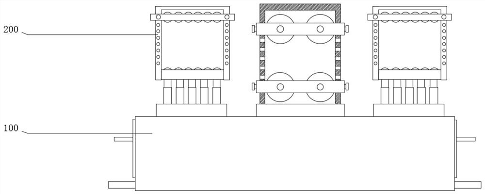
[0039] see Figure 1-7 , the present invention provides a technical solution: a steel rolling production equipment includes a base 100 and a rolling assembly 200, the base 100 is used to support and fix the rolling assembly 200, which is convenient for the adjustment and use of the rolling assembly 200, and is convenient for rolling steel materials of different specifications processing.

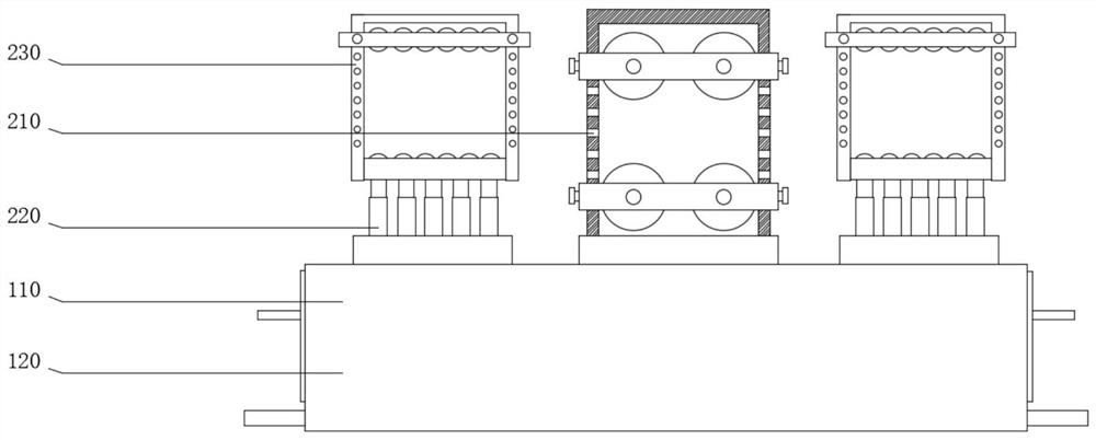
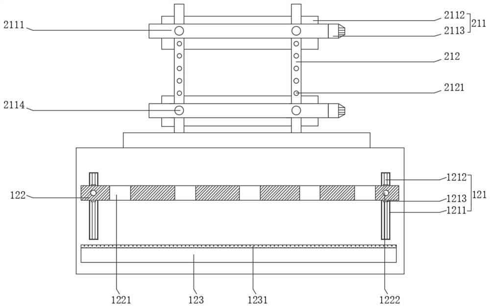
[0040] see Figure 1-Figure 3 , the base 100 includes a table body 110 and a placement frame 120, the placement frame 120 is arranged on both sides of the table body 110, the placement frame 120 includes a slide rail 121, a first plate body 122 and a second plate body 123, and the slide rail 121 is set to several The bottoms of several slide rails 121 are fixed on one side of the table body 110, and the first board body 122 is slidably connected with the table body 110 through the slide rails 121, which is convenient for adjusting the distance between the first board bod...

Example Embodiment

[0042] Example 2

[0043] see Figure 1-7 , the present invention provides a technical solution: a steel rolling production equipment includes a base 100 and a rolling assembly 200, the base 100 is used to support and fix the rolling assembly 200, which is convenient for the adjustment and use of the rolling assembly 200, and is convenient for rolling steel materials of different specifications processing.

[0044] see Figure 1-Figure 3 , the base 100 includes a table body 110 and a placement frame 120, the placement frame 120 is arranged on both sides of the table body 110, the placement frame 120 includes a slide rail 121, a first plate body 122 and a second plate body 123, and the slide rail 121 is set to several The bottoms of several slide rails 121 are fixed on one side of the table body 110, and the first board body 122 is slidably connected with the table body 110 through the slide rails 121, which is convenient for adjusting the distance between the first board bod...


PUM


Abstract

The invention provides steel calendaring production equipment, and belongs to the technical field of steel calendaring production. The steel calendaring production equipment comprises a base and calendaring assemblies. The base comprises a table body and a placement frame; the calendering assemblies comprise calendering pieces, telescopic pieces and pressing pieces; the calendering pieces comprise calendering parts and first supports; the first supports are fixed to the two sides of the top of the table body; the calendering parts comprise first groove bodies and calendering rollers; one sides of the first supports are slidably attached to the inner walls of the first groove bodies; the first groove bodies are in sliding connection with the first supports; the calendering rollers are rotationally arranged on the inner walls of the first groove bodies; and one ends of the calendering rollers rotationally penetrate through one sides of the first groove bodies. By adjusting the distance between the adjacent first groove bodies, adjustment and use can be conveniently conducted according to the specifications of calendered materials, and the application range of existing steel calendaring production equipment is conveniently widened, so that the machining efficiency of the steel calendaring production equipment is improved.

Description

technical field [0001] The invention relates to the technical field of steel rolling production, in particular to a steel rolling production equipment. Background technique [0002] Iron and steel rolling processing refers to the steel rolling industry, including steel plate, section steel, strip steel, wire rod, cold and hot sheet processing, etc. [0003] At present, the steel rolling production equipment used in the market is inconvenient to adjust and use according to the specifications of the rolling material in actual use, which makes the existing steel rolling production equipment poor in use effect, fixed in scope of application, and inconvenient to use for different rolling materials , which in turn leads to low efficiency of steel rolling processing. Contents of the invention [0004] In order to make up for the above deficiencies, the present invention provides a kind of steel rolling production equipment, which aims to improve the existing steel rolling produc...

Claims


Application Information

Patent Timeline
IPC IPC(8): B21B13/02B21B31/02B21B39/02
CPCB21B13/02B21B31/02B21B39/02B21B2013/021
Inventor 杨光涛
Owner 杨光涛
Why Eureka
Try Eureka