Molded product

Active Publication Date: 2020-01-02
HONDA MOTOR CO LTD +1
View PDF1 Cites 1 Cited by
  • Summary
  • Abstract
  • Description
  • Claims
  • Application Information

AI Technical Summary

Benefits of technology

[0004]Such a molded product often has differences in level (projections or recesses) on a surface of the body due to, for example, components accommodated inside the body of the molded product. The differences in level on the body cannot be removed by stick

Problems solved by technology

The differences in level on the body cannot be removed by sticking the design member to the surface of the body via the adhesive member and cause uneven parts

Method used


Image

  • Molded product
  • Molded product
  • Molded product

Examples


first embodiment

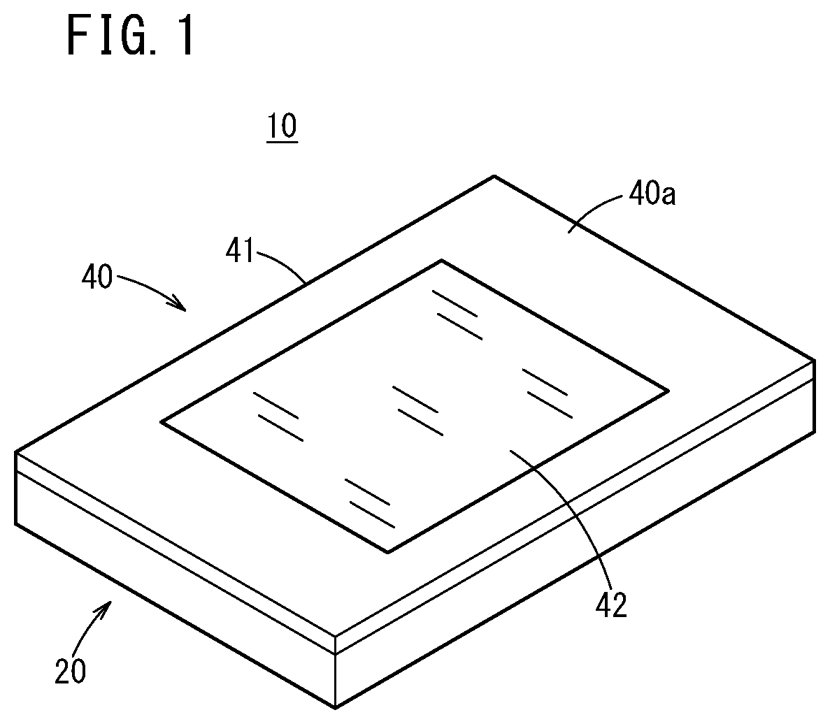
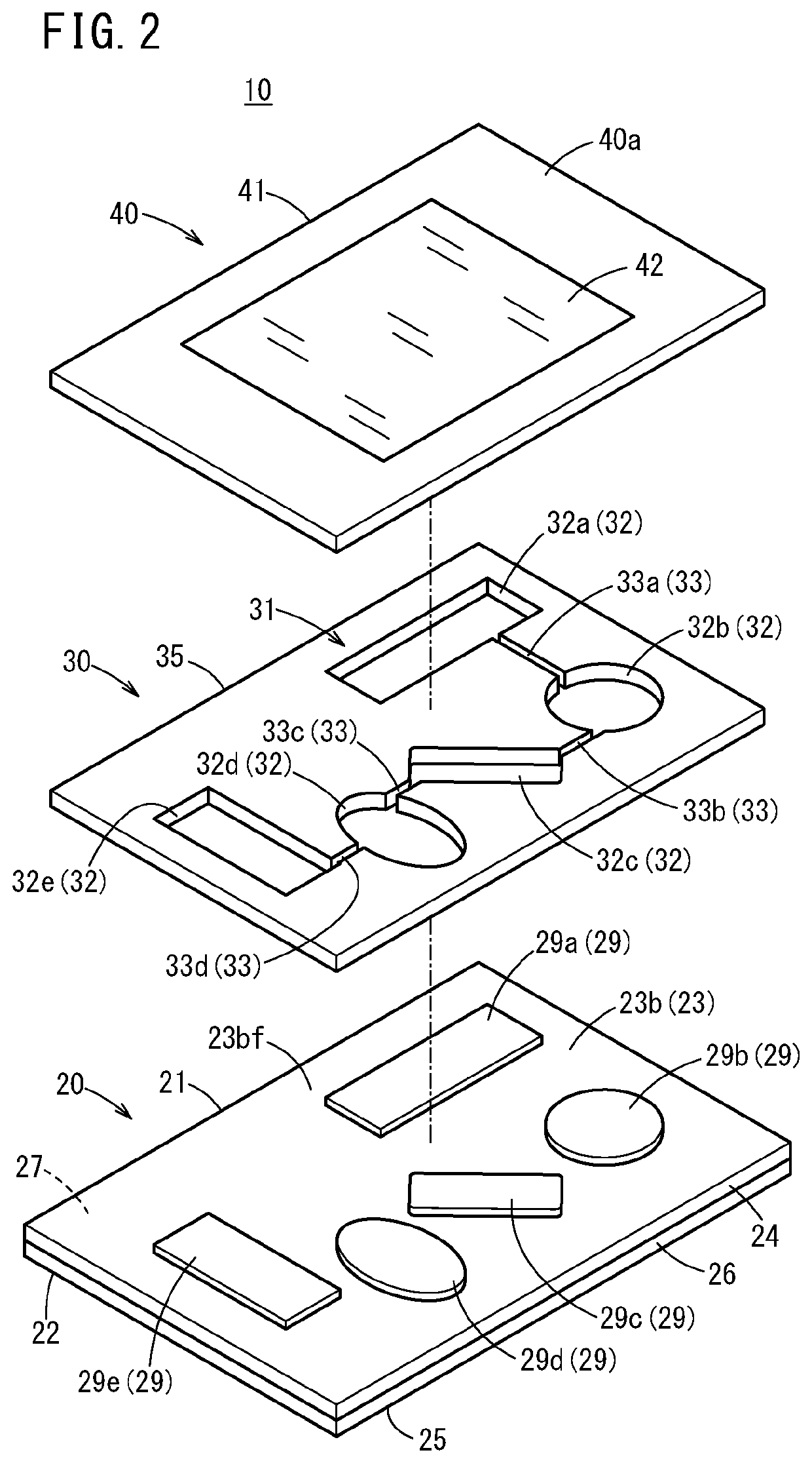
[0021]As illustrated in FIGS. 1 and 2, a molded product 10 according to a first embodiment of the present invention includes a body 20 and a design member 40 stuck to an outer surface of the body 20 via an adhesive member 30. Here, a card key is taken as an example of the molded product 10 according to the first embodiment. The card key has, for example, an information holding function allowing a user to get in a car (not illustrated) and to start the car.

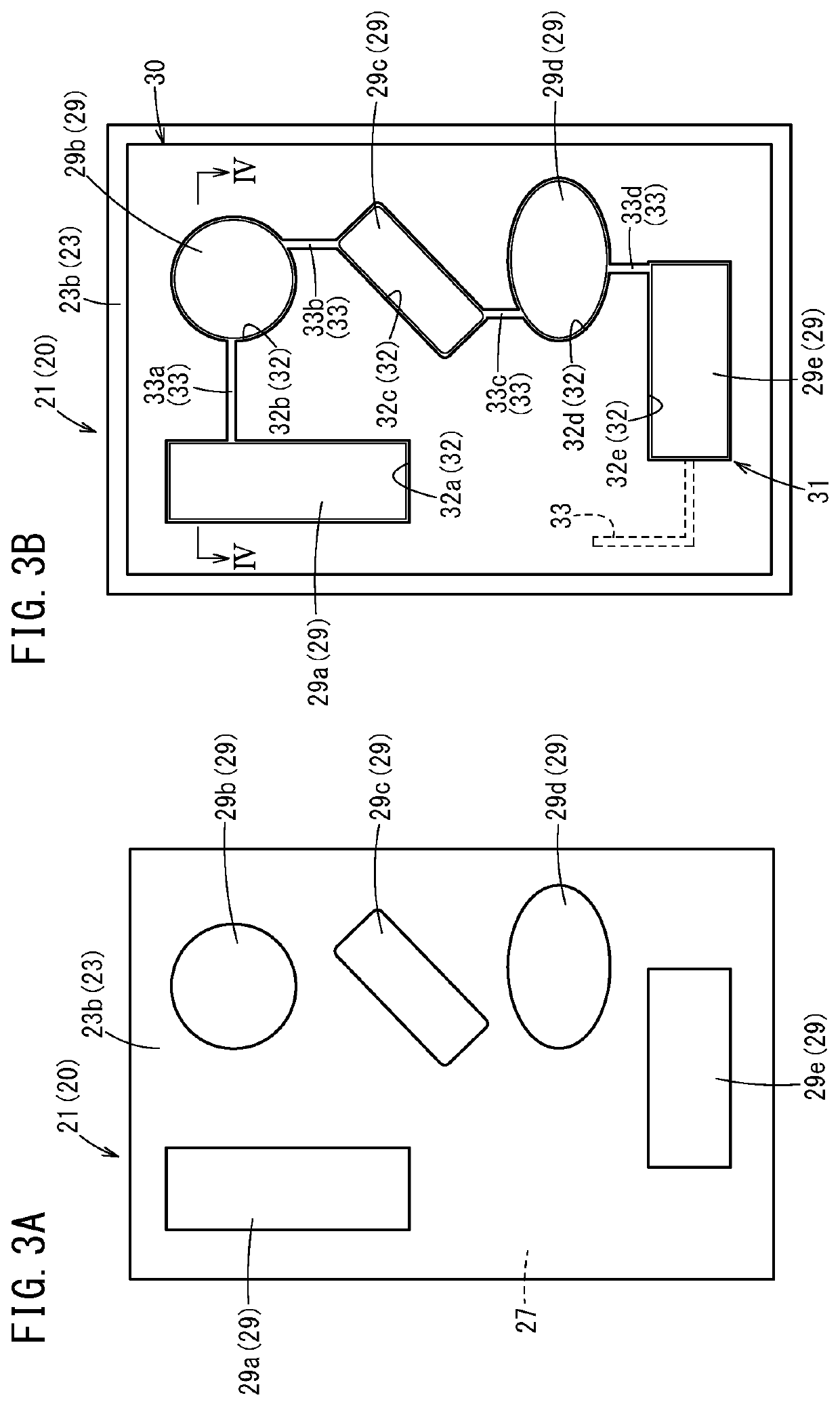
[0022]The body 20 of the molded product 10 is formed by stacking an upper case 21 on a lower case 22, both having a square U-shaped section. Specifically, the upper case 21 includes a roof portion 23 with a predetermined planar shape (rectangular shape in FIG. 2) and an upper protruding portion 24 protruding downward from the entire peripheral edge of the roof portion 23. The lower case 22 includes a bottom portion 25 with a planar shape identical to the planar shape of the upper case 21 and a lower protruding portion 26 protruding...

second embodiment

[0049]As illustrated in FIG. 6A, a molded product 10A according to a second embodiment is different from the molded product 10 according to the first embodiment in that an outer surface 52 of a portion (roof portion 51) of a body 50 to which the decorative sheet 41 is stuck is provided with a plurality of recesses 53. In the description below, the same reference numerals and symbols are used for components having identical structures or functions to those in the above-described embodiment, and the detailed descriptions thereof will be omitted.

[0050]For example, the roof portion 51 of the body 50 is provided with a first recess 53a and a second recess 53b having a predetermined depth from a flat part 52f of the outer surface 52 as the plurality of recesses 53. On the other hand, the adhesive member 30 sticking the decorative sheet 41 to the body 50 includes a buffer portion 36 connecting the first recess 53a and the second recess 53b.

[0051]Specifically, the buffer portion 36 include...

third embodiment

[0053]As in a molded product 10B according to a third embodiment illustrated in FIG. 6B, a body 60 (roof portion 61) may be provided with both a projection 29 and a recess 53. This structure also allows the design surface 42 of the decorative sheet 41 to be kept smooth due to a buffer portion 38 provided for the adhesive member 30. That is, the buffer portion 38 in this case includes an accommodation part 32 accommodating the projection 29 and a communication part 33 connecting the accommodation part 32 and the recess 53 (extending to a position facing the recess 53) of the body 60. This also allows the molded product 10B to operate similarly to the above-described molded product 10.

[0054]The molded products 10, 10A, and 10B according to the above-described embodiments produce the following advantageous effects.

[0055]The molded products 10 and 10B respectively include the buffer portions 31 and 38 formed by cutting off parts of the adhesive member 30 at positions corresponding at le...


PUM


Abstract

A molded product includes a body including a flat part and a projection protruding from the flat part, a design member including a design surface, and an adhesive member sticking the design member to the body. The adhesive member includes a buffer portion formed by cutting off a part of the adhesive member at a position corresponding at least to the projection. Thus, the adhesive member negates differences in level on the body, allowing the design surface to be smooth.

Description

CROSS-REFERENCE TO RELATED APPLICATION[0001]This application is based upon and claims the benefit of priority from Japanese Patent Application No. 2018-126033 filed on Jul. 2, 2018, the contents of which are incorporated herein by reference.BACKGROUND OF THE INVENTIONField of the Invention[0002]The present invention relates to molded products including bodies to which design members are stuck.Description of the Related Art[0003]To improve design quality, molded products are often provided with design members stuck to the bodies thereof. For example, Japanese Laid-Open Patent Publication No. 2005-113085 discloses a technique of sticking a substrate (design member) to an adherend (body). The design member has slotted grooves and is stacked on an adhesive layer (adhesive member) having through-passages at positions facing the slotted grooves. The through-passages and the slotted grooves lead the air existing between the adhesive member and the body to the outside when the design member...

Claims


Application Information

Patent Timeline
IPC IPC(8): B32B7/12B32B3/26
CPCB32B7/12B32B3/263C09J7/29C09J2301/206C09J2301/16C09J2301/204C09J2301/124B32B1/00Y10T428/24479Y10T428/24612B32B7/04B32B3/26Y10T428/23Y10T428/24802Y10T428/233Y10T428/24273Y10T428/231Y10T428/24314Y10T428/234Y10T428/24298Y10T428/24752Y10T428/24562Y10T428/24851
Inventor LEE, SEONGHUNTAKAHASHI, YUICHIKIYOMIYA, TOMOOMI
Owner HONDA MOTOR CO LTD
Why Eureka
Try Eureka