
Method of determining a path along an object, system and method for automatically inspecting an object

a technology of automatic inspection and path determination, applied in the direction of vehicle position/course/altitude control, process and machine control, instruments, etc., can solve the problems of drones neither being positioned at a constant distance, and the pilot's task is difficult to accomplish

Active Publication Date: 2020-01-02
TOP SEVEN GMBH & CO KG
View PDF0 Cites 5 Cited by
  • Summary
  • Abstract
  • Description
  • Claims
  • Application Information

AI Technical Summary

Benefits of technology

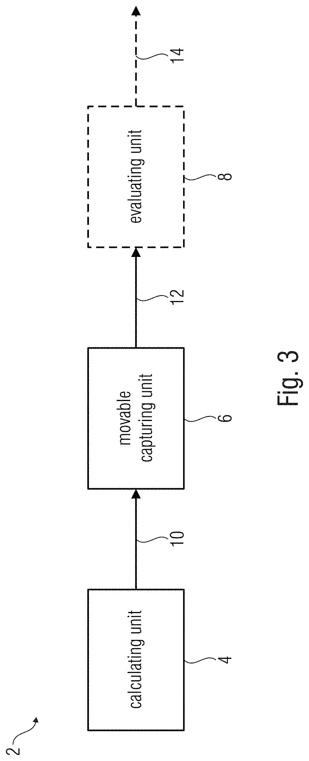
The present invention is about automating inspection of objects by determining the position of an object and creating a path to inspect it. The invention allows for adapting the path in real-time based on changing conditions. The invention also includes a calculating unit that determines trigger locations for a movable capturing unit based on the visual field of the capturing unit. The movable capturing unit is designed to capture images in a way that minimizes the number of pictures needed. The invention also compensates for aberrations and ensures that all surface areas of the object are captured.

Problems solved by technology

However, this has given rise to various disadvantages.
Particularly with objects that are far away, e.g., the blades of a wind turbine, this is difficult for the pilot to accomplish since for one thing, the camera becomes very small and sometimes is hardly visible and since, in addition, the head may be laid back far when objects are positioned at large height.
Controlling the camera by means of a monitor displaying the camera image also is no remedy since the only view available here is the first-person view of the camera rather than a top view of the drone.
In addition, both methods have the disadvantage that a specific location, for example where a defect has been recognized, can only be flown to again with a mere guess at its distance so as to inspect the location in more detail.
In addition, with this manual control, the drone can neither be positioned at a constant distance from an object, nor can the camera be precisely aligned with the object, nor can exact trigger points of a camera for taking pictures of the object be defined.
Thus, measuring (or dimensioning), i.e., determining a magnitude of possible errors, is rendered more difficult since the field of view of the image is not known.
A potential defect may then be seen in the pictures, which will not be clearly discernable in the general survey picture, however.

Method used


Image

  • Method of determining a path along an object, system and method for automatically inspecting an object
  • Method of determining a path along an object, system and method for automatically inspecting an object
  • Method of determining a path along an object, system and method for automatically inspecting an object

Examples


Embodiment Construction

[0032]In the description of the figures which follows, elements which are identical or identical in action will be provided with identical reference numerals, so that their descriptions in the different embodiments are mutually exchangeable.

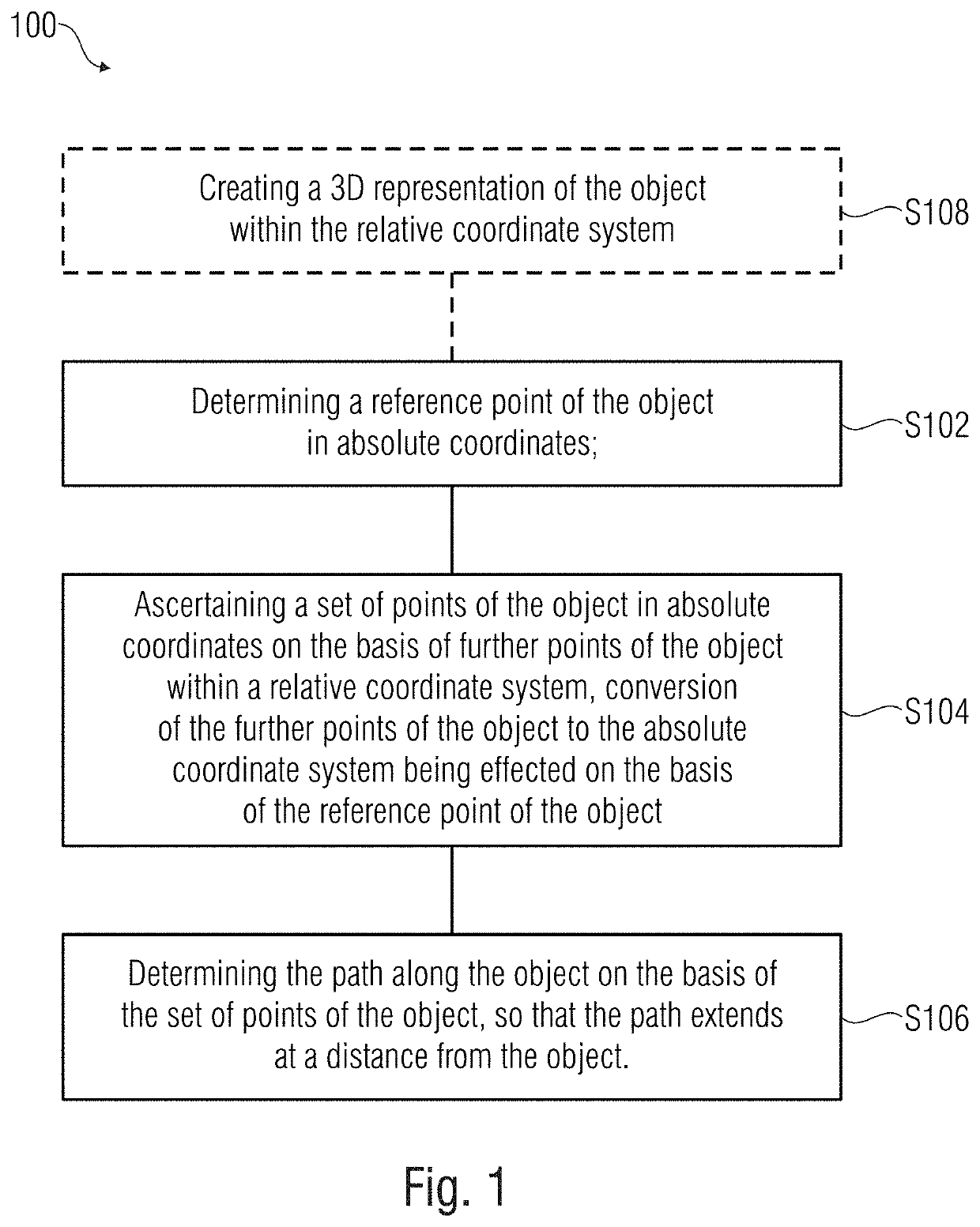
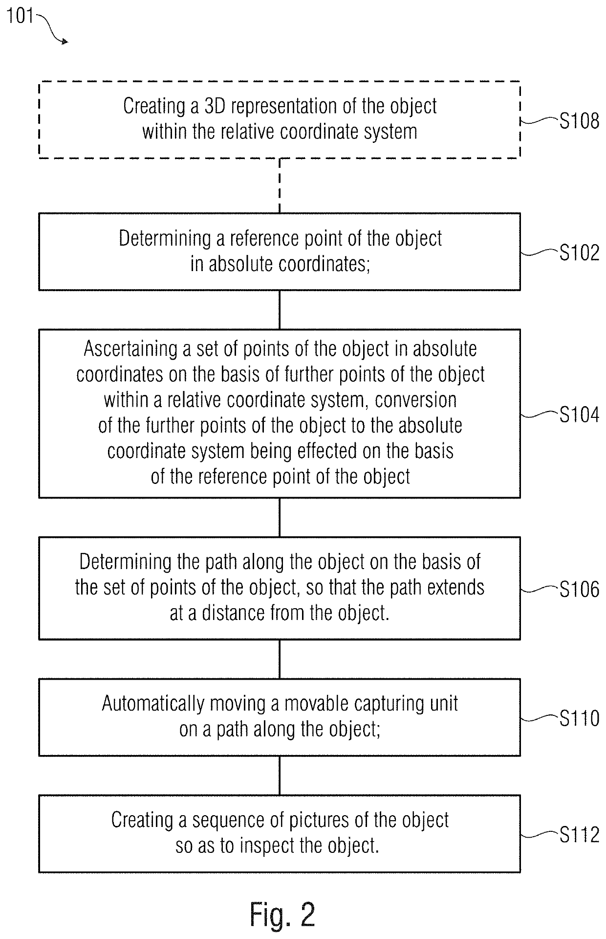
[0033]FIG. 1 shows a schematic block representation of a method 100 of determining a path along one or more objects; to simplify matters, one single object shall be used as the basis without prejudice to the general validity. The path is a flight route, a travel route, a diving route, etc., for example, and in embodiments it is (or its points are) determined in three dimensions, or directions in space. The method 100 comprises the steps S102, S104 and S106. Step S102 includes determining a reference point of the object in absolute coordinates. The absolute coordinates are GPS coordinates, for example, i.e., coordinates within a coordinate system related to the Earth and / or an absolute geographic coordinate system (geo-centered coordinate system. ...


PUM


Abstract

A method of determining a path along an object includes a step of “determining a reference point of the object in absolute coordinates”, a step of “ascertaining a set of points of the object in absolute coordinates on the basis of further points of the object within a relative coordinate system, conversion of the further points of the object to the absolute coordinate system being effected on the basis of the reference point of the object”, and a step of “determining the path along the object on the basis of the set of points of the object, so that the path extends at a distance from the object”.

Description

CROSS-REFERENCES TO RELATED APPLICATIONS[0001]This application is a continuation of copending International Application No. PCT / EP2017 / 083355, filed Dec. 18, 2017, which is incorporated herein by reference in its entirety, and additionally claims priority from German Applications Nos. DE 10 2017 204 242.7, filed Mar. 14, 2017, and DE 10 2017 205 647.9, filed Apr. 3, 2017, both of which are incorporated herein by reference in their entirety.[0002]The present invention relates to a method of determining a path along an object and to a system and a method for automatically inspecting an object. Embodiments relate to a camera drone which automatically flies a distance along an object so as to take photos of the object and to detect potential damage. Further embodiments show flight path scheduling on the basis of 3D CAD (computer-aided design) models interlaced with geographic GPS (global positioning system) data.BACKGROUND OF THE INVENTION[0003]Up to now, cameras installed on, e.g., dro...

Claims


Application Information

Patent Timeline
Patent Type & Authority Applications(United States)
IPC IPC(8): G08G5/00G06F17/50G06T17/05G07C5/08G05D1/00B64C39/02
CPCB64C2201/12G06T17/05G06F17/5095G07C5/0808G05D1/0027B64C39/024G07C5/0816G08G5/0034G05D1/0094G03B15/006G08G5/0069G08G5/025B64U2101/26G05D1/106G06F30/15G05D1/69G05D1/40B64U2201/10
Inventor SCHICKEL, PETERSENG, ULRICHNEUBAUER, OLIVER
Owner TOP SEVEN GMBH & CO KG
Learn More