Methods for Generating Interfacial Surfaces and Devices Therefor

a technology of facial surfaces and generators, applied in the field of facial surface generators and methods of generating interfacial surfaces, to achieve the effects of reducing (or eliminating), reducing layer rearrangement, and increasing slip

Active Publication Date: 2020-01-09
MATERIAL ANSWERS LLC
View PDF0 Cites 1 Cited by
  • Summary
  • Abstract
  • Description
  • Claims
  • Application Information

AI Technical Summary

Benefits of technology

[0013]The ability to actively convey material through the ISG using drag flow reduces (or eliminates) the need for pressure driven flow, which has many advantages. First, a low-pressure flow of molten polymer is less susceptible to abrupt changes in velocity that can cause defects related to unstable flow. Second, the use of low pressure flow opens up the potential to use alternative low-friction housing materials that will increase slip at the polymer / wall interface. Increasing slip has been shown to reduce layer rearrangement resulting from second normal stress differences. Materials such as polytetrafluoroethylene (PTFE) that are incompatible with the high stresses in ISGs fed by pressure-driven flow are now potential candidates. Third, it may be possible to introduce additives or coatings into the multilayer flow during the layer multiplication process. Introduction of additional materials at the layer interface may be used to address issues with adhesion and / or impart additional functionality. Fourth, processing of very high viscosity polymer materials, such as rubbers, that are incompatible with ISG's fed by pressure-driven flow may now be possible.

Problems solved by technology

Second, the use of low pressure flow opens up the potential to use alternative low-friction housing materials that will increase slip at the polymer / wall interface.

Method used


Image

  • Methods for Generating Interfacial Surfaces and Devices Therefor
  • Methods for Generating Interfacial Surfaces and Devices Therefor
  • Methods for Generating Interfacial Surfaces and Devices Therefor

Examples


example 1

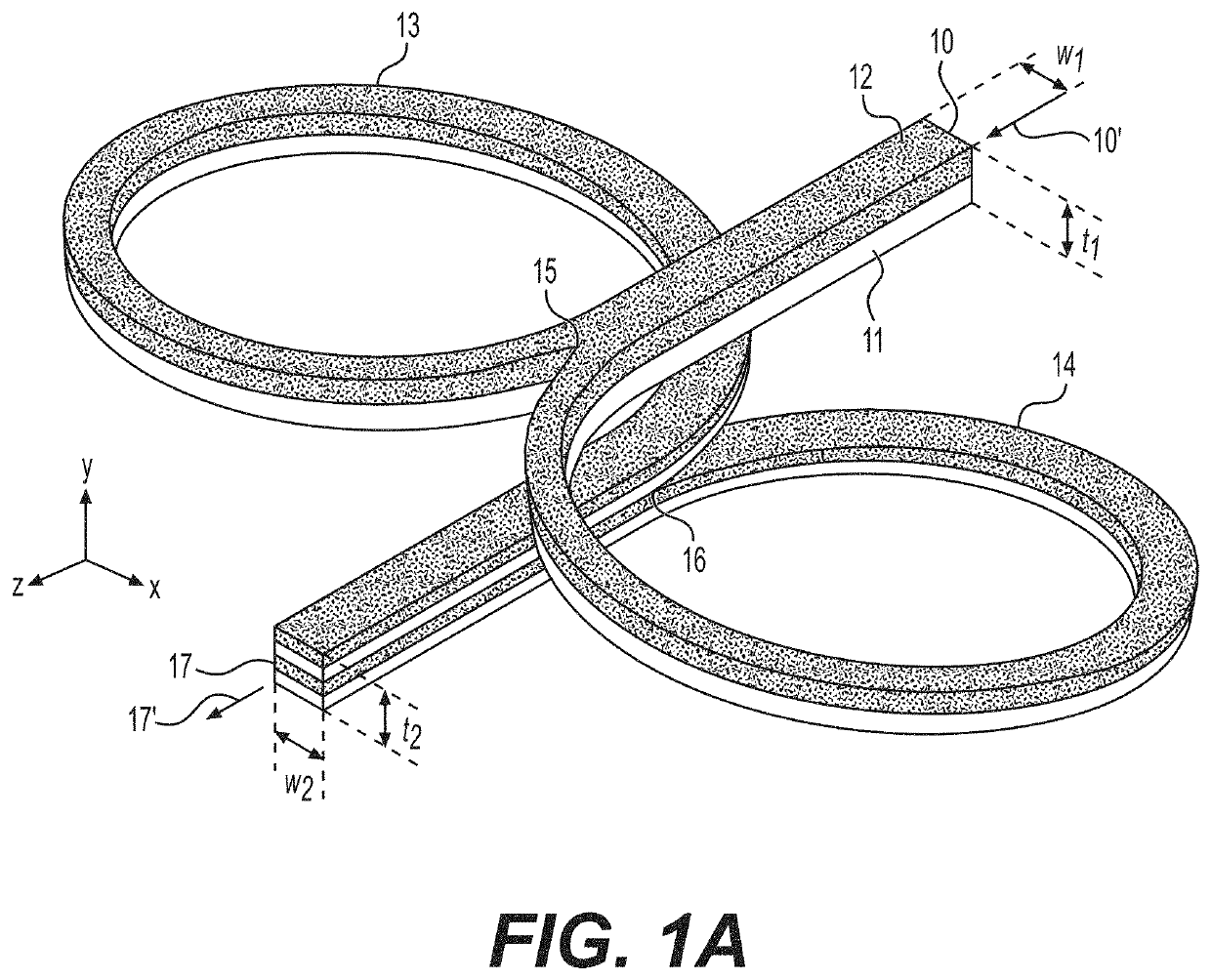
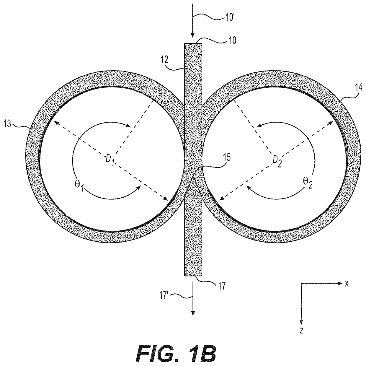
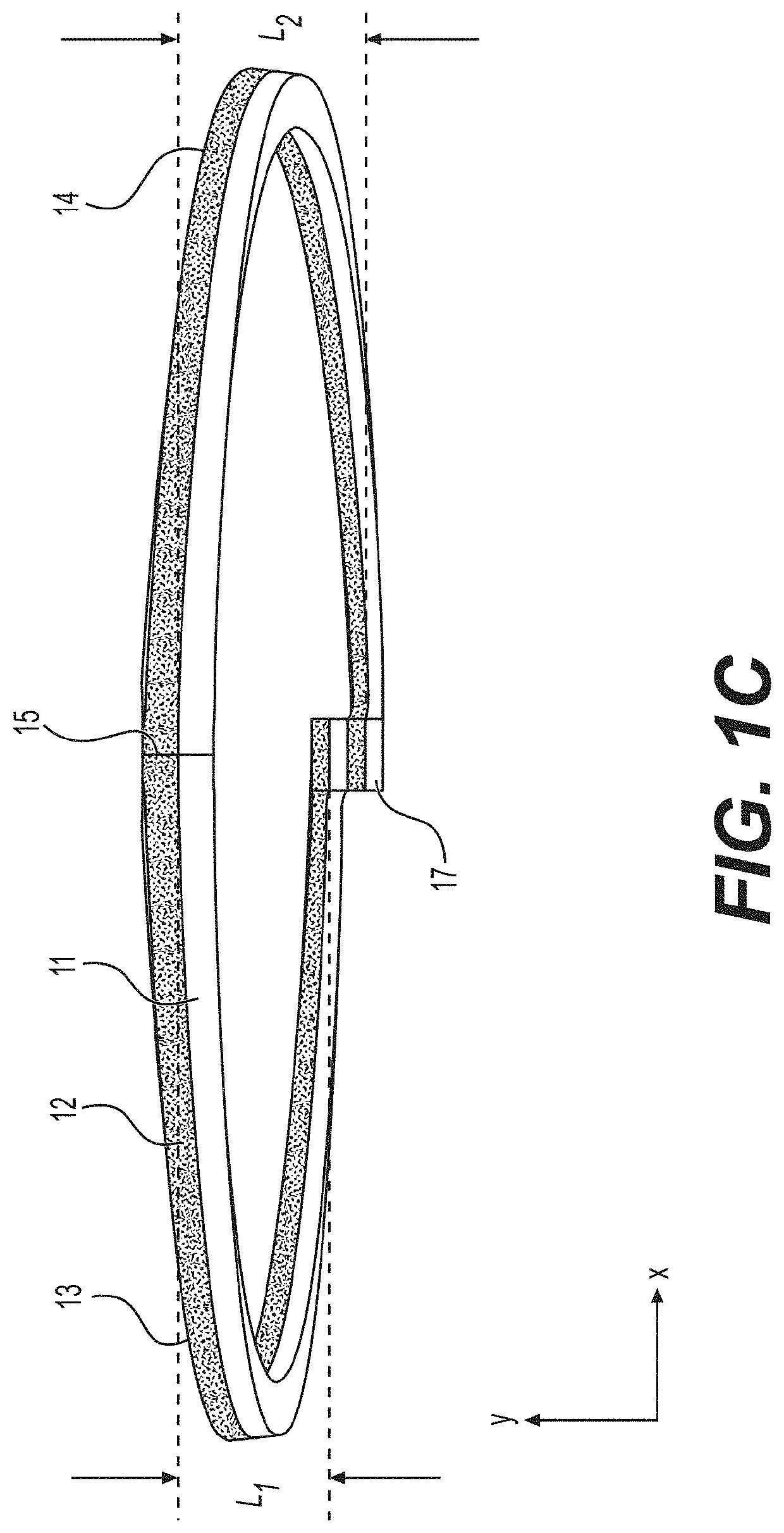
[0095]An ISG apparatus, similar to the exemplary apparatus shown in FIG. 2, was fabricated to demonstrate its operation under the condition where materials are conveyed through the apparatus by way of pressure. The apparatus was designed to subject an initial two-layer composite stream to a single layer multiplication cycle to form a second composite stream with four layers. The apparatus was configured and operated to generate interfacial surfaces according to the method illustrated in FIGS. 1A-1D.

[0096]An apparatus housing was fabricated as a single component from acrylonitrile butadiene styrene (ABS) plastic using an additive manufacturing (3D printing) process. Internal flow path conduits were formed within the housing during the additive manufacturing process—no subsequent manufacturing processes (additive or subtractive) were required. The housing was oriented such that the inlet conduit was on the top surface and the outlet was on the bottom surface. The housing was raised up...

example 2

[0099]An ISG apparatus with counter rotating rotors, similar to the exemplary apparatus shown in FIG. 4, was fabricated to demonstrate its operation under the condition where materials are conveyed through the apparatus by way of drag, or Couette, flow induced by the rotation of two counter-rotating rotors. The apparatus was designed to subject an initial two-layer composite stream to a single layer multiplication cycle to form a second composite stream with four layers. The apparatus was configured and operated to generate interfacial surfaces according to the method illustrated in FIGS. 1A-1D.

[0100]An apparatus housing was fabricated as two components, similar to the exemplary housing shown in FIG. 4, from ABS plastic using an additive manufacturing process. Flow path conduits were formed in the housing components during the additive manufacturing process—no subsequent manufacturing processes (additive or subtractive) were required to fabricate the housing. The housing was oriente...

example 3

[0104]The apparatus from Example 2 is reconfigured and operated to generate interfacial surfaces according to the method illustrated in FIGS. 5A-5D. The same polymer materials from Example 2 are used. The apparatus housing is reoriented such that the outlet from Example 2 is positioned to be on the top surface and the inlet is positioned to be on the bottom surface. The dual cavity reservoir is placed on the new top surface and rotated 90-degrees relative the orientation used in Example 2. The two reservoir cavities are then filled—one with polymer material A and one with polymer material B.

[0105]To operate the apparatus, the electric motor is powered on and allowed to rotate continuously at a speed of approximately 3 revolutions per minute (rpm) in the opposite direction that was used in Example 2. Polymer materials A and B are gravity-fed into the apparatus inlet (the outlet from Example 2), forming an initial two-layer composite stream with an approximate 50:50 layer ratio. The i...


PUM

PropertyMeasurementUnit
arc angleaaaaaaaaaa
lead anglesaaaaaaaaaa
diameteraaaaaaaaaa

Abstract

Embodiments of the present invention include a novel interfacial surface generator (ISG) design comprised of helical channels and associated methods of using the new design. The novel design addresses processing challenges associated with conventional ISG designs used in layer multiplying coextrusion systems. Embodiments of the present invention may be used in either a static configuration or “active” configuration. In one active configuration, two counter-rotating cylindrical rods and / or moving belts may be used to induce drag, or Couette, flow. Conveyance of materials through the ISG may be due to pressure driven flow, drag flow, or a combination of these.

Description

CROSS-REFERENCE TO RELATED APPLICATIONS[0001]This application claims the benefit of U.S. Provisional Application No. 62 / 695,572, filed on Jul. 9, 2018, the entire contents of which are incorporated by reference herein.FIELD OF THE INVENTION[0002]The present invention relates to interfacial surface generators and to methods of generating interfacial surfaces in a flowable material.BACKGROUND OF THE INVENTION[0003]Layer-multiplying coextrusion (LMC) is an innovative processing technique that is used to fabricate micro- and nano-layered polymer composites that are comprised of two or more polymeric materials. The unique physical, mechanical, and electrical properties of these multilayer materials have been exploited by industry to generate novel commercial products in the areas of packaging, filtration, optics, energy storage, and data storage. Expanding the use of LMC to generate new materials and products is an active area of research; however, current LMC technology severely limits ...

Claims


Application Information

Patent Timeline
Patent Type & Authority Applications(United States)
IPC IPC(8): B29C48/71B29C48/255B29C48/21
CPCB29C48/71B29C48/21B29C48/255B29C48/08
Inventor WINROTH, SCOTT ALLENSCOTT, CHRISTOPHER E.
Owner MATERIAL ANSWERS LLC
Why Eureka
Try Eureka