
Pressure optimized sourcing of cabin pressurization and component air cooling

Active Publication Date: 2020-01-09
HAMILTON SUNDSTRAND CORP
View PDF6 Cites 2 Cited by
  • Summary
  • Abstract
  • Description
  • Claims
  • Application Information

AI Technical Summary

Benefits of technology

The patent describes an environmental control system (ECS) for aircraft that includes a cooling turbine and a turbine bypass valve. The turbine bypass valve directs a portion of the ECS output airflow to a first air load at a higher pressure, while another portion of the airflow is directed to a second air load at a lower pressure for cooling purposes. The ECS also includes an outlet heat exchanger and a condensing heat exchanger. The technical effect of this system is to provide efficient cooling of the ECS output airflow and to improve the overall performance of the ECS.

Problems solved by technology

Providing pressurized airflow from the ECS when it is not necessary is less than optimal operation of the ECS and reduces system cooling capacity, or alternatively requires the usage of larger and higher weight heat exchangers than is necessary.

Method used


Image

  • Pressure optimized sourcing of cabin pressurization and component air cooling
  • Pressure optimized sourcing of cabin pressurization and component air cooling

Examples


Embodiment Construction

[0022]A detailed description of one or more embodiments of the disclosed apparatus and method are presented herein by way of exemplification and not limitation with reference to the Figures.

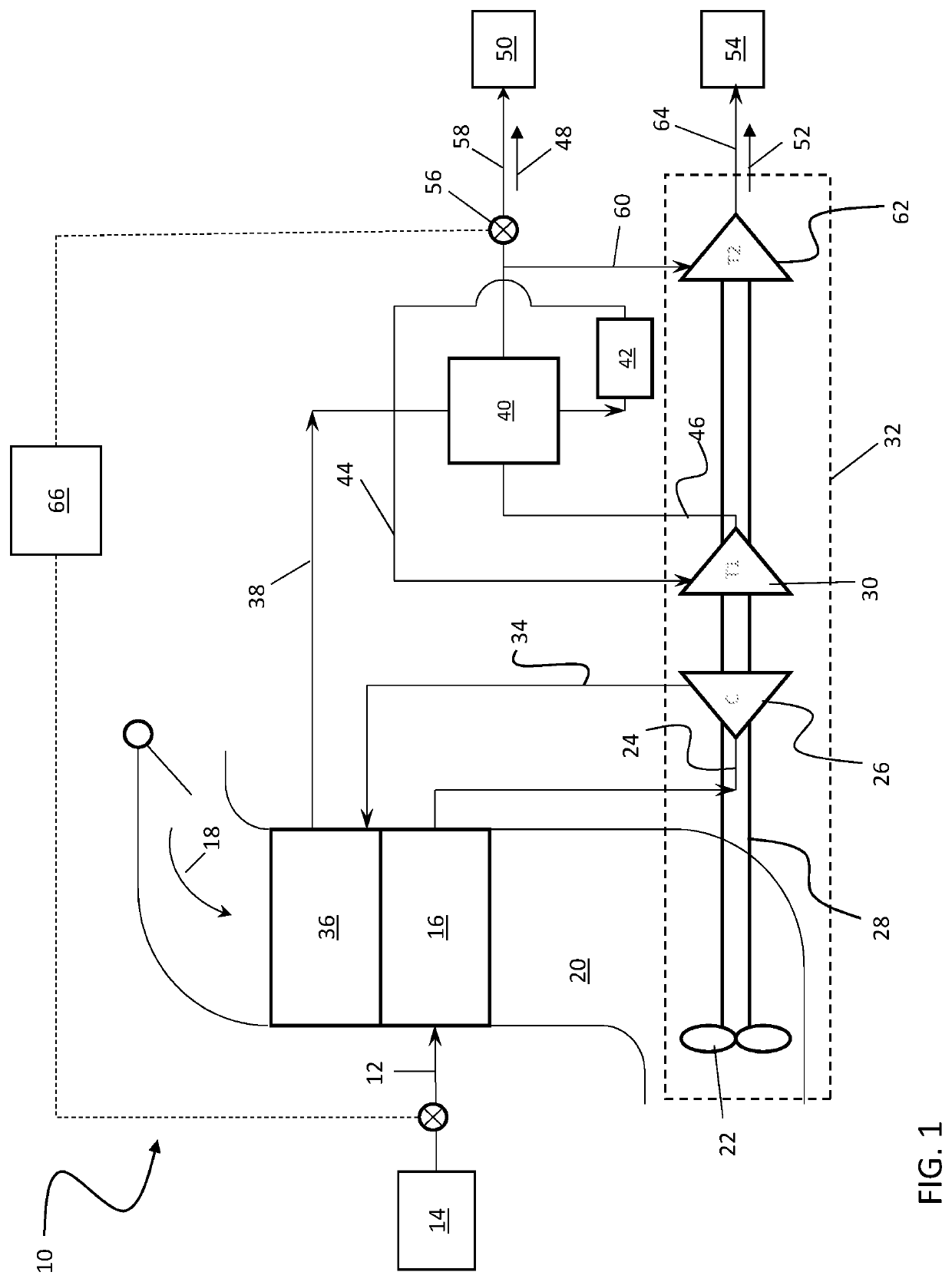
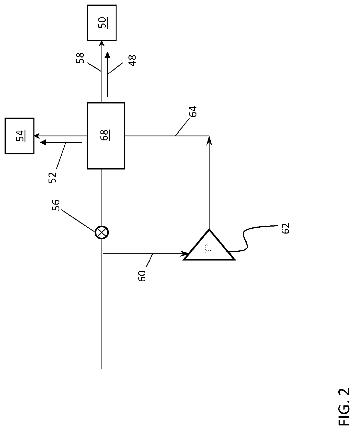
[0023]Referring to FIG. 1 an environmental control system (ECS) 10 is supplied with a bleed airflow 12 from, for example, a compressor bleed air supply system 14 of a gas turbine engine (not shown). The bleed airflow 12 is input into a primary heat exchanger 16 such that the bleed airflow 12 is in a thermal energy exchange with a ram airflow 18, or an ambient airflow, directed along a ram airflow passage 20. In some embodiments, the ram airflow 18 is driven along the ram airflow passage 20 via a fan 22. The bleed airflow 12 is cooled in the primary heat exchanger 16 via thermal energy exchange with the ram airflow 18, and is communicated along a compressor inlet passage 24 to a compressor 26. The bleed airflow 12 is then compressed to a higher pressure at the compressor 26. In some embodiments, t...


PUM


Abstract

An environmental control system (ECS) for an aircraft includes at least one cooling turbine, and a turbine bypass valve disposed fluidly upstream of the at least one cooling turbine. The turbine bypass valve is configured to direct a first portion of an ECS output airflow to a first air load at a first pressure via a first outlet passage, and direct a second portion of the ECS output airflow across a cooling turbine of the at least one cooling turbine and to a second air load at a second pressure lower than the first pressure for cooling thereof.

Description

STATEMENT OF FEDERAL SUPPORT[0001]This invention was made with Government support under contract D6004-F3359-3359-2410001 awarded by the United States Air Force. The Government has certain rights in the invention.BACKGROUND[0002]Exemplary embodiments pertain to the art of aircraft environmental control systems (ECSs), and in particular to ECSs having an air cycle machine and distribution of cooling airflow therefrom.[0003]Many aircraft utilize ECS configurations to provide conditioned air to fulfill the functions of providing pressurization to a cockpit / cabin area of the aircraft and for cooling components such as avionics or other electronics of the aircraft. While pressurization of the conditioned air is needed for the cockpit / cabin areas, the airflow for component cooling may not require pressurization. Providing pressurized airflow from the ECS when it is not necessary is less than optimal operation of the ECS and reduces system cooling capacity, or alternatively requires the u...

Claims


Application Information

Patent Timeline
IPC IPC(8): B64D13/08B64D13/04F02C6/08
CPCB64D13/04B64D2013/0618F02C6/08B64D13/08B64D13/06B64D2013/0614B64D2013/0629
Inventor HO, TONYRETERSDORF, ALAN
Owner HAMILTON SUNDSTRAND CORP
Learn More