
Valve arrangement and valve guide

a valve arrangement and valve guide technology, applied in the direction of engines, mechanical equipment, machines/engines, etc., can solve the problems of increasing the torque and power of the engine, the available torque of the engine during take-off is often inadequate, and the performance of the engine equipped with a turbocharger is poor, etc., to achieve accurate axial positioning of the groove and time- and cost-efficient

Active Publication Date: 2020-01-09
VOLVO LASTVAGNAR AB
View PDF4 Cites 0 Cited by
  • Summary
  • Abstract
  • Description
  • Claims
  • Application Information

AI Technical Summary

Benefits of technology

The present patent text discusses the use of turbo chargers in combustion engines and how they work to increase torque and power. The text also mentions the use of an aperture, which can be a hole or a drilled hole, to facilitate the efficient production of the turbo charger. The technical effect of the patent is the improvement of engine performance using turbo chargers with a circular aperture, which can be produced cost- and time-efficiently.

Problems solved by technology

This means that a larger amount of fuel can be fed to a combustion chamber in an engine, thus increasing the torque and power of the engine.
In turbocharged diesel engines intended for, for example, commercial vehicles the available torque from the engine during take-off is often somewhat inadequate.
The reason for this is that an engine equipped with a turbocharger performs worse than a normally aspirated engine at low rpm's due to that the turbo charger is a hindrance of the aspiration.
The fact that the engine has a take-off performance which is worse than a normally aspirated engine means that the amount of air which is typical for a turbocharged diesel engine is not supplied.
The above-mentioned sequence of events is furthermore unfavorable since it contributes to reduced performance during the take-off phase of the engine.
The engine will furthermore be perceived by users as “insufficient” during the take-off phase, since it has been necessary to limit the amount of fuel supplied during the initial “aspirating engine” phase, also known as turbo-lag.

Method used


Image

  • Valve arrangement and valve guide
  • Valve arrangement and valve guide
  • Valve arrangement and valve guide

Examples


Embodiment Construction

[0053]The present invention will now be described more fully hereinafter with reference to the accompanying drawings, in which currently preferred embodiments of the invention are shown. This invention may, however, be embodied in many different forms and should not be construed as limited to the embodiments set forth herein; rather, these embodiments are provided for thoroughness and completeness, and fully convey the scope of the invention to the skilled addressee. Like reference characters refer to like elements throughout.

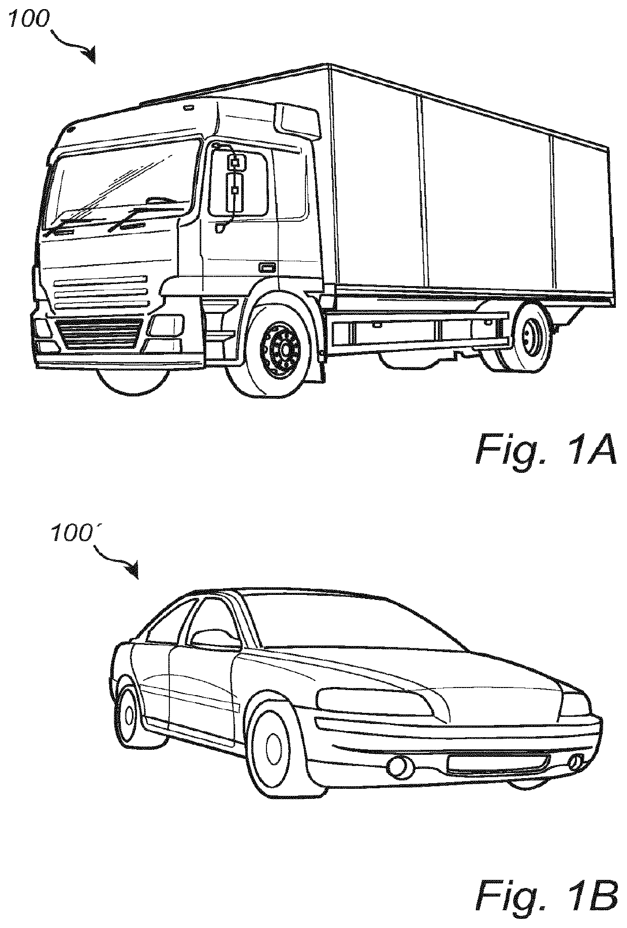
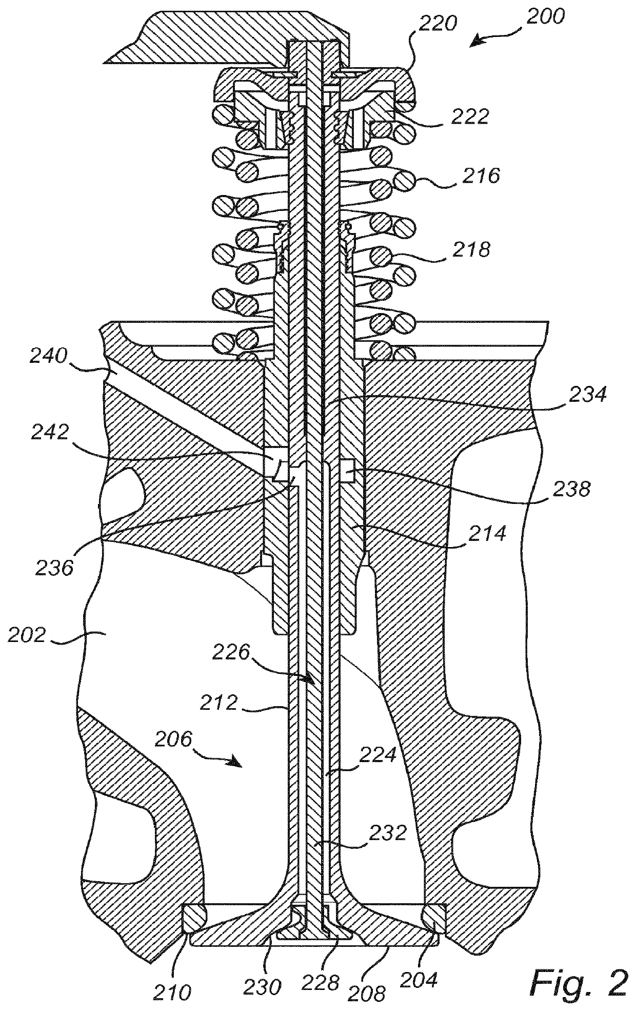
[0054]Referring now to the drawings and to FIGS. 1A, 1B, and 2 in particular, there is in FIG. 1A depicted an exemplary vehicle, here illustrated as a truck 100 comprising an engine in which a valve arrangement according to the present invention may be incorporated. The valve arrangement may of course be implemented also in a car 100′, as shown in FIG. 1B, a working machine or in any engine, such a stationary engine, having a supply of compressed air.

[0055]The ...


PUM


Abstract

A valve arrangement for supplying air to an internal combustion engine includes a first valve and a second valve arranged within the first valve. A valve guide for use in a valve arrangement is also provided.

Description

CROSS REFERENCE TO RELATED APPLICATIONS[0001]This application is a Continuation of U.S. patent application Ser. No. 15 / 755,332, filed Feb. 26, 2018, which is a 371 application of International Application No. PCT / EP2015 / 078857, filed Dec. 7, 2015, which claims priority to International Application No. PCT / EP2015 / 070560, filed Sep. 9, 2015.BACKGROUND AND SUMMARY[0002]The invention relates to a valve arrangement for supplying air to an internal combustion engine. The invention further relates to a valve guide for such a valve arrangement.[0003]In connection with combustion engines, turbo chargers are often utilized which comprise a turbine which is driven by the flow of exhaust gases. The energy which is thus absorbed by the turbine is then transferred via a shaft to a compressor which is arranged to compress the air on the intake side of the combustion engine and thus increase the amount of air in the combustion chamber. This means that a larger amount of fuel can be fed to a combust...

Claims


Application Information

Patent Timeline
Patent Type & Authority Applications(United States)
IPC IPC(8): F01L1/28F01L3/08F02M23/00F01L3/06
CPCF02M23/006F01L1/28F01L3/06F01L3/08Y02T10/12
Inventor SVENSSON, STIG ARNELANGERVIK, LENNART
Owner VOLVO LASTVAGNAR AB
Learn More