Tail rotor system including an electric motor

Inactive Publication Date: 2020-01-16
SIKORSKY AIRCRAFT CORP
View PDF0 Cites 2 Cited by
  • Summary
  • Abstract
  • Description
  • Claims
  • Application Information

AI Technical Summary

Benefits of technology

This patent describes a tail rotor system for a vertical takeoff and landing (VTOL) aircraft that includes an electric motor connected to the tail rotor drive shaft. The electric motor can be mounted directly about the tail rotor drive shaft or adjacent to another electric motor. The electric motor can be connected to an energy storage device and can operate as a generator to deliver power to the tail rotor drive shaft. The system also includes a controller that can activate the electric motor based on the torque, power, and rotor speed requirements of the VTOL aircraft. The presence or absence of the electric motor and energy storage device can be recognized, and the power requirements of the aircraft management system can be updated accordingly. The technical effect of this patent is to provide a more efficient and flexible tail rotor system for VTOL aircraft that can improve performance and reliability.

Problems solved by technology

This gross weight limitation includes weight of the air vehicle itself including fuel, passengers, crew and cargo.
Operation type as well as weather conditions may place constraints on gross vehicle weight limits.
That is, wind, rain, temperature, humidity, operational, and other factors may limit take-off weight below that of a max gross weight for the air vehicle.
Reducing take-off weight may negatively affect mission performance

Method used


Image

  • Tail rotor system including an electric motor

Examples


Embodiment Construction

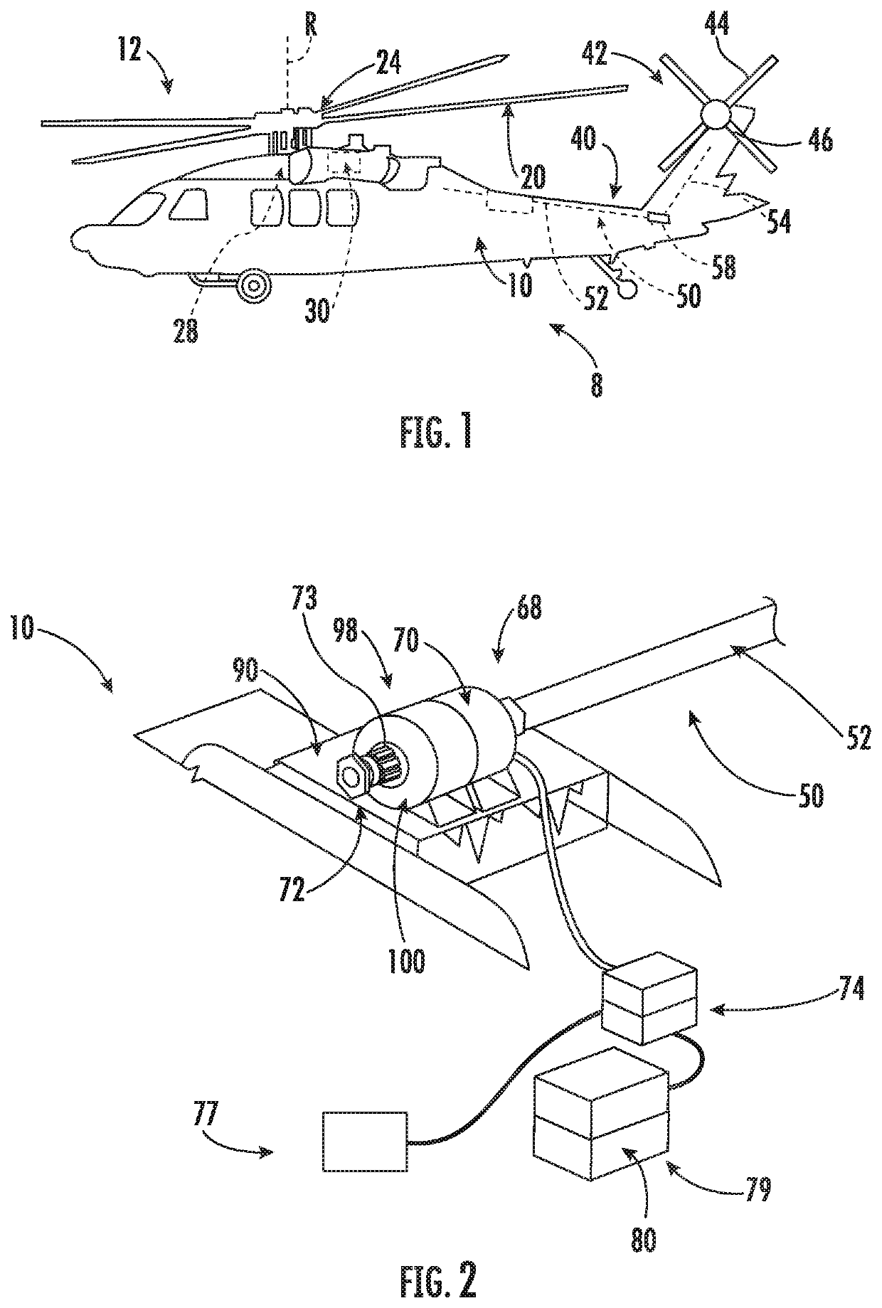
[0027]A vertical takeoff and landing (VTOL) or rotary wing aircraft, in accordance with an exemplary embodiment, is generally indicated at 8 in FIG. 1. Rotary wing aircraft 8 including a fuselage 10 that supports a main rotor system 12, which rotates about a main rotor axis R. Main rotor system 12 includes a plurality of rotor blades 20 rotatable about a main rotor axis “R”. Plurality of rotor blades 20 is mounted to a rotor hub 24.

[0028]Main rotor system 12 is driven by a gear system 28 coupled to one or more prime movers, indicated generally at 30. Aircraft 8 includes an extending tail 40 that supports a tail rotor system 42 including a plurality of tail rotor blades, indicated generally at 44 supported by a tail rotor hub 46. Tail rotor system 42 may be operatively coupled to gear system 28 through a tail rotor drive shaft 50. Tail rotor drive shaft 50 includes a first shaft portion 52 extending from gear system 28 and a second shaft portion 54 extending to tail rotor hub 46. Fir...


PUM


Abstract

A tail rotor system for an aircraft includes a tail rotor hub, a tail rotor drive shaft mechanically connected to the tail rotor hub, and an electric motor coupled to the tail rotor drive shaft.

Description

BACKGROUND[0001]The subject matter disclosed herein generally relates to the art of air vehicles and, more particularly, to a tail rotor system including an electric motor.[0002]Air vehicles, such as rotary wing aircraft, typically include a main rotor system which provides lift and a tail rotor system that may provide yaw control or forward propulsion. In some arrangements, the main rotor system may also provide forward propulsion. One or more engines provide power to the main and tail rotor systems. Air vehicles typically include an aircraft maximum gross weight limitation. This gross weight limitation includes weight of the air vehicle itself including fuel, passengers, crew and cargo.[0003]Various conditions may reduce flight operations below a maximum gross vehicle weight. Operation type as well as weather conditions may place constraints on gross vehicle weight limits. That is, wind, rain, temperature, humidity, operational, and other factors may limit take-off weight below th...

Claims


Application Information

Patent Timeline
IPC IPC(8): B64C27/82B64C27/06B64C27/14H02K11/00
CPCH02K11/0094B64C27/06B64C2027/8209B64C27/14B64C27/82B64D27/24Y02T50/40Y02T50/60
Inventor WALTNER, PETER J.MACKO, NIKOLAS ANDREWBAZZANI, DANIEL
Owner SIKORSKY AIRCRAFT CORP
Why Eureka
Try Eureka