This helps you quickly interpret patents by identifying the three key elements:
Problems solved by technology
Method used
Benefits of technology
Benefits of technology
The present patent provides a wind power generation device that can improve on conventional devices. The device uses a spiral blade and magnetic modules to effectively utilize wind and generate electricity. The device also ensures synchronous rotation of the magnetic modules for efficient energy production. The technical effects include improved wind power utilization and enhanced energy production through synchronous rotation of magnetic modules.
Problems solved by technology
However, electricity generated from the conventional wind power generation device by utilizing the wind to rotate the large blade is extremely limited.
Method used
Image
Click on the blue label to locate the original text in one second.
Reading with bidirectional positioning of images and text.
Examples
first embodiment
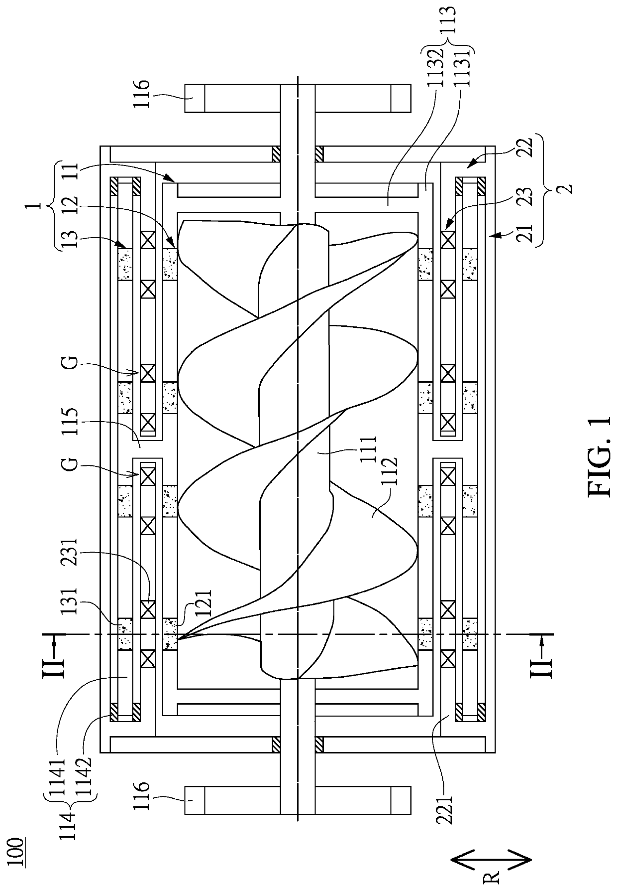
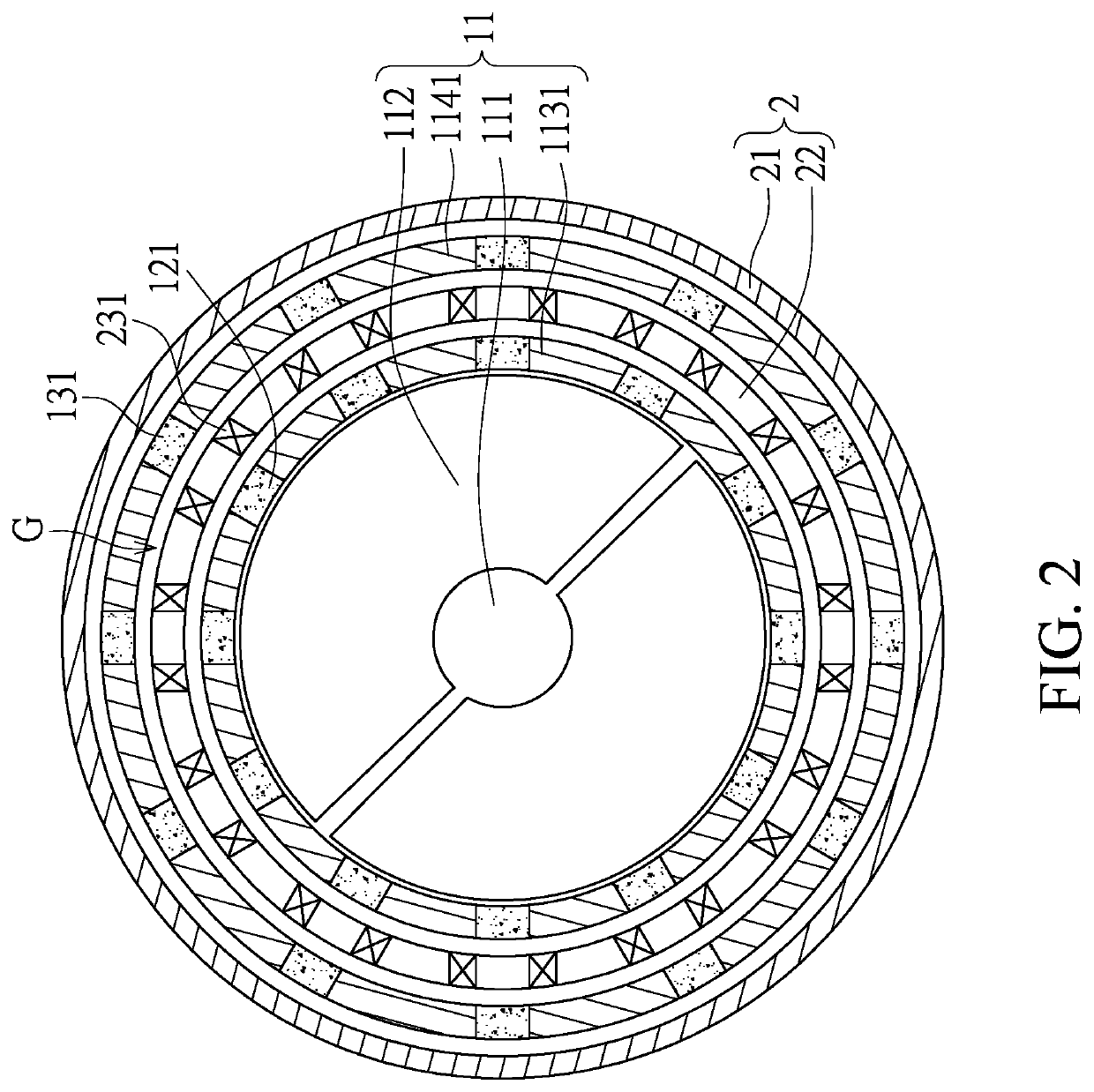
[0022]Referring to FIG. 1 and FIG. 2, a first embodiment of the present disclosure provides a wind power generation device 100, which includes a rotor assembly 1 and a stator assembly 2 arranged outside of the rotator assembly 1. The rotator assembly 1 includes a rotating member 11, a first magnetic module 12 disposed on the rotating member 11, and a second magnetic module 13 disposed on the rotating member 11 and arranged outside of the first magnetic module 12.
[0023]The rotating member 11 has a column 111, a spiral blade 112 connected to an outer surface of the column 111, a first carrier 113 fixed to the column 111, a second carrier 114 arranged outside of the first carrier 113, a connecting member 115 connecting the first carrier 113 and the second carrier 114, and two wind guides 116 respectively fixed to two opposite ends of the column 111.
[0024]Moreover, the spiral blade 112 has a length along a central axis of the column 111, and the length is greater than 0.5 pitch of the s...
second embodiment
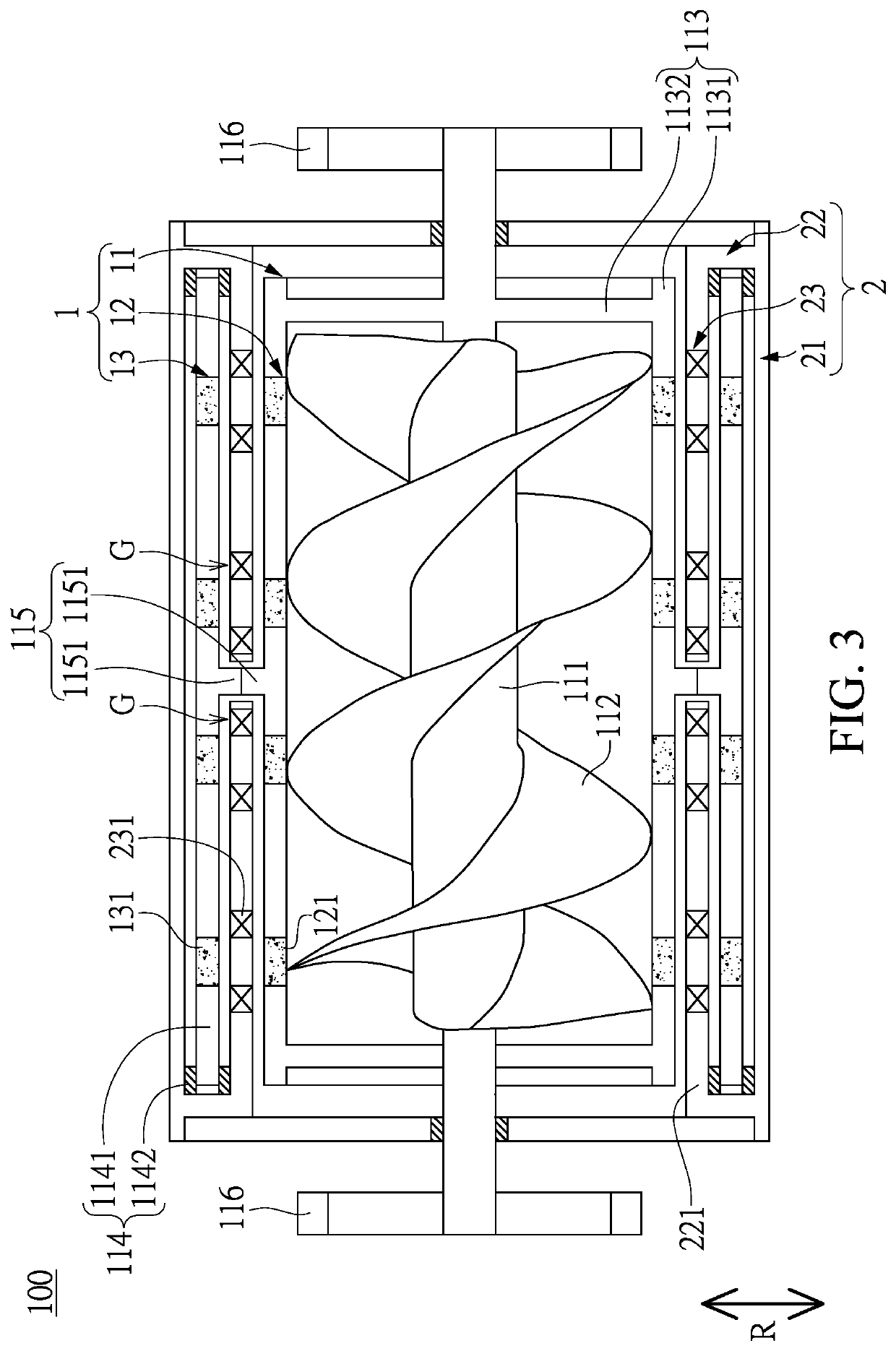
[0040]Referring to FIG. 3, a second embodiment of the present disclosure is similar to the first embodiment of the present disclosure, so that descriptions of the same components in the first and second embodiments of the present disclosure will be omitted for the sake of brevity, the main difference between the first and second embodiments being the rotating member 11.
[0041]Specifically, the connecting member 115 of the rotating member 11 in the present embodiment includes two gears 1151 meshingly engaged with each other, and the two gears 1151 are respectively fixed to the inner hollow cylinder 1131 and the outer hollow cylinder 1141. When the spiral blade 112 drives the first carrier 113 to rotate, the first carrier 113 synchronously rotates the outer hollow cylinder 1141 (i.e., the first carrier 113 and the outer hollow cylinder 1141 are rotated at the same speed) through the cooperation of the two gears 1151.
third embodiment
[0042]Referring to FIG. 4, a third embodiment of the present disclosure is similar to the first embodiment of the present disclosure, so that descriptions of the same components in the first and third embodiments of the present disclosure will be omitted for the sake of brevity, the main difference between the first and third embodiments being the rotating member 11.
[0043]Specifically, the rotating member 11 of the present embodiment excludes the connecting member 115, and the inner hollow cylinder 1131 and the outer hollow cylinder 1141 are separated from each other. When the spiral blade 112 drives the first carrier 113 to rotate, the first carrier 113 synchronously rotates the outer hollow cylinder 1141 (i.e., the first carrier 113 and the outer hollow cylinder 1141 are rotated at the same speed) only by using the first magnetic module 12 to magnetically connect to the second magnetic module 13.
PUM
Abstract
A wind power generation device includes a rotor assembly and a stator. The rotor assembly includes a rotating member, a first magnetic module, and a second magnetic module the latter two of which are fixed on the rotating member. The rotating member has a column and a spiral blade connected to the column. The first and second magnetic modules are arranged outside the spiral blade and face each other. The rotor assembly defines an annular gap formed around the spiral blade and between the first and second magnetic modules. The stator assembly includes a frame, a positioning member connected to the frame, and an induction module fixed on the positioning member and arranged in the annular gap. The spiral blade can rotate the rotator assembly relative to the stator assembly by wind, so that a region between the first and second magnetic module sweeps over the induction module.
Description
CROSS-REFERENCE TO RELATED PATENT APPLICATION[0001]This application claims the benefit of priority to PCT Patent Application No. PCT / JP2018 / 003788, filed on Feb. 5, 2018. The entire content of the above identified application is incorporated herein by reference.[0002]This PCT Patent Application claims priority from the Taiwan Patent Application No. 106103818, filed Feb. 6, 2017, which application is incorporated herein by reference in its entirety.[0003]Some references, which may include patents, patent applications and various publications, may be cited and discussed in the description of this disclosure. The citation and / or discussion of such references is provided merely to clarify the description of the present disclosure and is not an admission that any such reference is “prior art” to the disclosure described herein. All references cited and discussed in this specification are incorporated herein by reference in their entireties and to the same extent as if each reference was ...
Claims
Application Information
Patent Timeline
Application Date:The date an application was filed.
Publication Date:The date a patent or application was officially published.
First Publication Date:The earliest publication date of a patent with the same application number.
Issue Date:Publication date of the patent grant document.
PCT Entry Date:The Entry date of PCT National Phase.
Estimated Expiry Date:The statutory expiry date of a patent right according to the Patent Law, and it is the longest term of protection that the patent right can achieve without the termination of the patent right due to other reasons(Term extension factor has been taken into account ).
Invalid Date:Actual expiry date is based on effective date or publication date of legal transaction data of invalid patent.

