Display device with touch sensor

Active Publication Date: 2020-01-16
JAPAN DISPLAY INC
View PDF0 Cites 6 Cited by
  • Summary
  • Abstract
  • Description
  • Claims
  • Application Information

AI Technical Summary

Benefits of technology

[0005]One or more embodiments of the present invention have been made in view of the above, an object thereof

Problems solved by technology

However, in that case, since the lead-out wiring needs to pass over the outer edge of a sealing film for sealing a

Method used


Image

  • Display device with touch sensor
  • Display device with touch sensor
  • Display device with touch sensor

Examples


Embodiment Construction

[0021]Hereinafter, embodiments of the present invention will be described with reference to drawings. The disclosure is merely an example, and appropriate modifications that those skilled in the art could easily conceive of without departing from the spirit of the invention, of course, are included in the scope of the present invention. In addition, in order to make the description clearer, the drawings may schematically represent the width, thickness, shape of each part, as compared with the embodiments, but are merely examples and do not limit the interpretation of the present invention. In the specification and the drawings, the same elements as those described above with reference to the drawings already described may be denoted by the same reference numerals, and the detailed description thereof may be appropriately omitted.

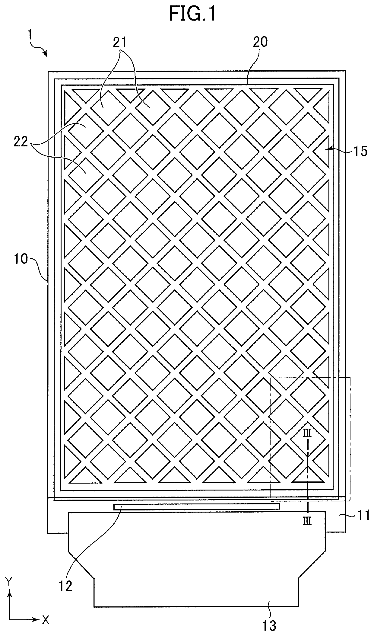
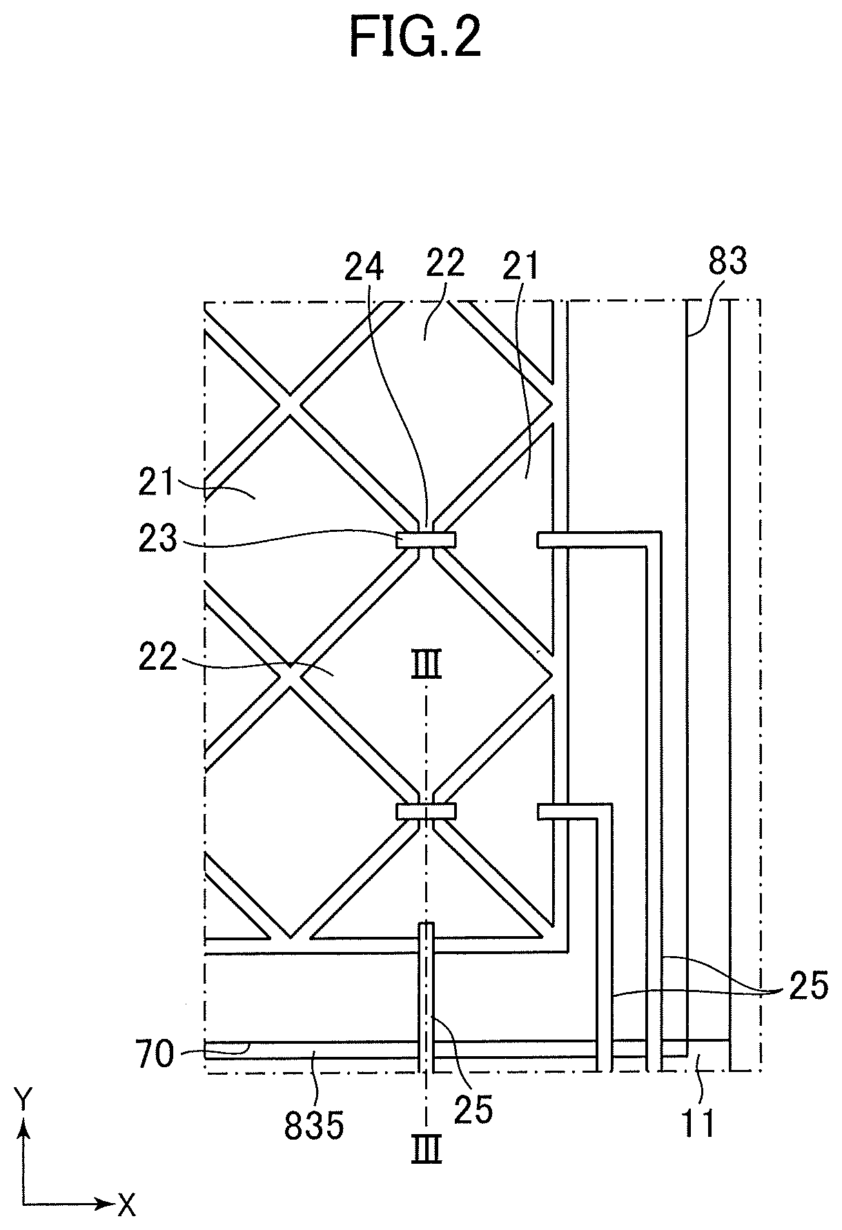
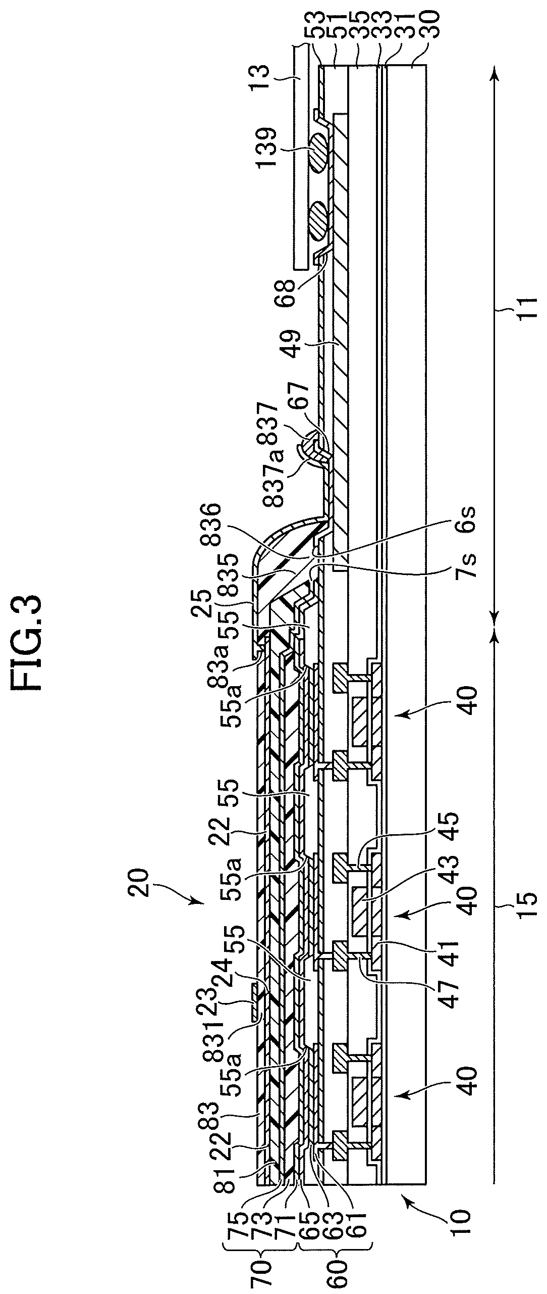
[0022]FIG. 1 is a plan view of a display device with a touch sensor (hereinafter, also simply referred to as a display device) according to an embodiment. F...


PUM


Abstract

A display device according to an embodiment of the invention includes: a base insulating film; a sealing film which covers the base insulating film; a plurality of first electrodes which are two-dimensionally arranged on the sealing film, the first electrodes adjacent in a first direction being connected via a first connection line; a plurality of second electrodes which are two-dimensionally arranged, the second electrodes adjacent in the second direction being connected via a second connection line intersecting the first connection line in plan view; an interlayer insulating film which is interposed between the first connection line and the second connection line and which fills a step formed by an outer edge of the sealing film and the base insulating film; and a lead-out wiring which is connected to the first electrode or the second electrode and which passes over a portion of the interlayer insulating film which fills the step.

Description

CROSS-REFERENCE TO RELATED APPLICATION[0001]This application is a continuation under 35 U.S.C. 120 of International Application PCT / JP2018 / 001944 having the International Filing Date of Jan. 23, 2018, and having the benefit of the earlier filing date of Japanese Application No. 2017-061230, filed on Mar. 27, 2017. Each of the identified applications is fully incorporated herein by reference.BACKGROUND OF THE INVENTION1. Field of the Invention[0002]One or more embodiments of the present invention relate to a display device with a touch sensor.2. Description of the Related Art[0003]JP2015-050245A discloses a display device incorporating a capacitive touch sensor in which a first electrode extending in an X direction in which adjacent main body portions are connected via a connection portion, and a second electrode extending in a Y direction in which adjacent main body portions are connected via a connection portion are disposed with a sealing film interposed therebetween.SUMMARY OF TH...

Claims


Application Information

Patent Timeline
IPC IPC(8): G06F3/044
CPCG06F2203/04111G06F3/0445H01L27/323G06F3/0443G06F3/0446H05B33/02H05B33/04H05B33/06H05B33/12H05B33/22G09F9/00G09F9/30G06F3/0412G06F3/04164G06F2203/04103H10K59/131H10K77/111H10K50/8426H10K50/844H10K59/1201G06F3/044H10K59/00H10K50/00G06F3/041H10K59/40
Inventor MIYAMOTO, MITSUHIDEAKIMOTO, HAJIMEMATSUMOTO, YUKOTADA, YUSUKE
Owner JAPAN DISPLAY INC
Why Eureka
Try Eureka