
Coil electronic component and manufacturing method thereof

a technology of electronic components and coils, applied in the direction of inductances, inductances with magnetic cores, cores/yokes, etc., can solve the problems of low productivity and low rated current requirements of standard ferrite inductors, and achieve excellent dc-bias characteristics

Active Publication Date: 2020-01-16
SAMSUNG ELECTRO MECHANICS CO LTD
View PDF10 Cites 1 Cited by
  • Summary
  • Abstract
  • Description
  • Claims
  • Application Information

AI Technical Summary

Benefits of technology

[0007]An aspect of the present disclosure may provide a coil electronic component having excellent DC-bias characteristics by inserting a pillar-shaped core part into the coil electronic component. The disclosure further provides a method of manufacturing the coil electronic component using a magnetic sheet.

Problems solved by technology

In parallel with recent developments in portable devices such as a smartphones, tablet personal computers (PC), and the like, the use of high-speed application processing units (APU) and large area displays has increased, such that required amounts of rated current may not be obtained with standard ferrite inductors.
However, these winding type inductors have a disadvantage in that productivity thereof may be low.

Method used


Image

  • Coil electronic component and manufacturing method thereof
  • Coil electronic component and manufacturing method thereof
  • Coil electronic component and manufacturing method thereof

Examples


Embodiment Construction

[0015]Hereinafter, exemplary embodiments of the present disclosure will be described in detail with reference to the accompanying drawings.

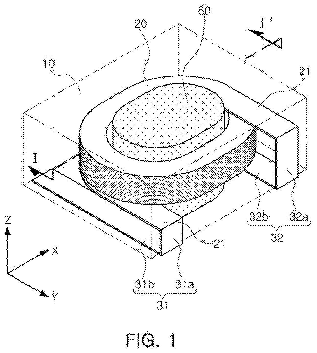
[0016]FIG. 1 is a schematic perspective view illustrating a coil electronic component according to an exemplary embodiment in which a coil, leads, a pillar-shaped core, and external terminals are visible.

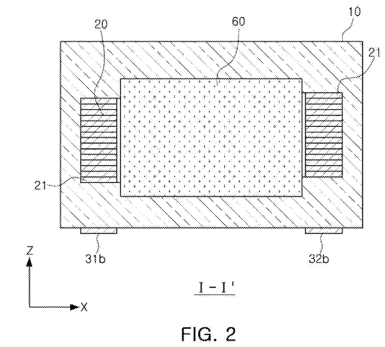
[0017]FIG. 2 is a cross-sectional view taken along line I-I′ of FIG. 1.

[0018]Referring to FIGS. 1 and 2, the coil electronic component according to the exemplary embodiment includes a body 10 in which a winding coil part 20 having leads 21 is disposed, and external terminals 31 and 32 connected to the winding coil part 20 through the leads 21 and disposed on an external surface of the body 10.

[0019]The body 10 may have a lower surface provided as amounting surface, an upper surface opposing the lower surface, end surfaces disposed opposite each other in a length direction, and side surfaces disposed opposite each other in a width direction.

[0020]...


PUM

PropertyMeasurementUnit
temperatureaaaaaaaaaa
widthaaaaaaaaaa
thicknessaaaaaaaaaa

Abstract

A coil electronic component includes a body and external terminals. The body includes a winding coil part and a pillar-shaped core part inserted inside of the winding coil part and formed of a magnetic metal. The external terminals are connected to the winding coil part and disposed on an external surface of the body. The body contains the magnetic metal and a resin, and the pillar-shaped core part has magnetic permeability higher than that of a portion of the body disposed outside of the winding coil part.

Description

CROSS-REFERENCE TO RELATED APPLICATION(S)[0001]This application is the Divisional Application of U.S. patent application Ser. No. 15 / 391,228 filed on Dec. 27, 2019, which claims benefit of priority to Korean Patent Application No. 10-2016-0046210 filed on Apr. 15, 2016 in the Korean Intellectual Property Office, the disclosures of which are incorporated herein by reference in their entirety.BACKGROUND1. Field[0002]The present disclosure relates to a coil electronic component and a manufacturing method thereof.2. Description of Related Art[0003]An inductor is an electronic component, and is a representative passive element used in electronic circuits together with resistors and capacitors to remove noise therefrom.[0004]In parallel with recent developments in portable devices such as a smartphones, tablet personal computers (PC), and the like, the use of high-speed application processing units (APU) and large area displays has increased, such that required amounts of rated current ma...

Claims


Application Information

Patent Timeline
Patent Type & Authority Applications(United States)
IPC IPC(8): H01F27/255H01F41/02H01F27/29H01F27/28H01F41/076H01F41/061
CPCH01F41/076H01F27/2828H01F27/292H01F41/061H01F41/0233H01F27/255H01F41/0246H01F17/04H01F27/245H01F27/263H01F2003/106H01F2017/046H01F2017/048H01F17/045H01F17/0033H01F27/2847H01F41/04
Inventor KIM, HYUNG HOKIM, YONG SUKCHANG, GUN SEYOO, YOUNG SEUCK
Owner SAMSUNG ELECTRO MECHANICS CO LTD
Learn More