Fuel cell separator and fuel cell stack

a technology of separator and fuel cell, applied in the direction of fuel cells, collectors/separators, fuel cell details, etc., can solve the problem of center-folding of beads, and achieve the effect of simple configuration

Active Publication Date: 2020-01-16
HONDA MOTOR CO LTD
View PDF0 Cites 2 Cited by
  • Summary
  • Abstract
  • Description
  • Claims
  • Application Information

AI Technical Summary

Benefits of technology

[0006]The present invention has been devised while taking into consideration the aforementioned circumstances, and has the object of providing a fuel cell separator and a fuel cell stack having a bead which is capable of forming a suitable seal with a simple configuration.
[0007]In order to realize the aforementioned object, one aspect of the present invention is characterized by a fuel cell separator formed in a plate shape and including a bead configured to form a seal for preventing leakage of fluid, wherein the bead is formed integrally with the fuel cell separator, and when viewed in cross section, protrudes from a plate surface of the fuel cell separator together with being formed in a multistage trapezoidal shape.

Problems solved by technology

However, in a case that the root portion of the bead is hard (a strong restraining force is acting thereon) due to the shape of the location where the bead is provided or the like, the root portion does not undergo elastic expansion, and therefore, there is a possibility that the portion where sealing is being performed by the protruding end portion (the tip end part) of the bead may undergo center-folding (buckling).

Method used


Image

  • Fuel cell separator and fuel cell stack
  • Fuel cell separator and fuel cell stack
  • Fuel cell separator and fuel cell stack

Examples


Embodiment Construction

[0021]Preferred embodiments of the present invention will be presented and described in detail below with reference to the accompanying drawings.

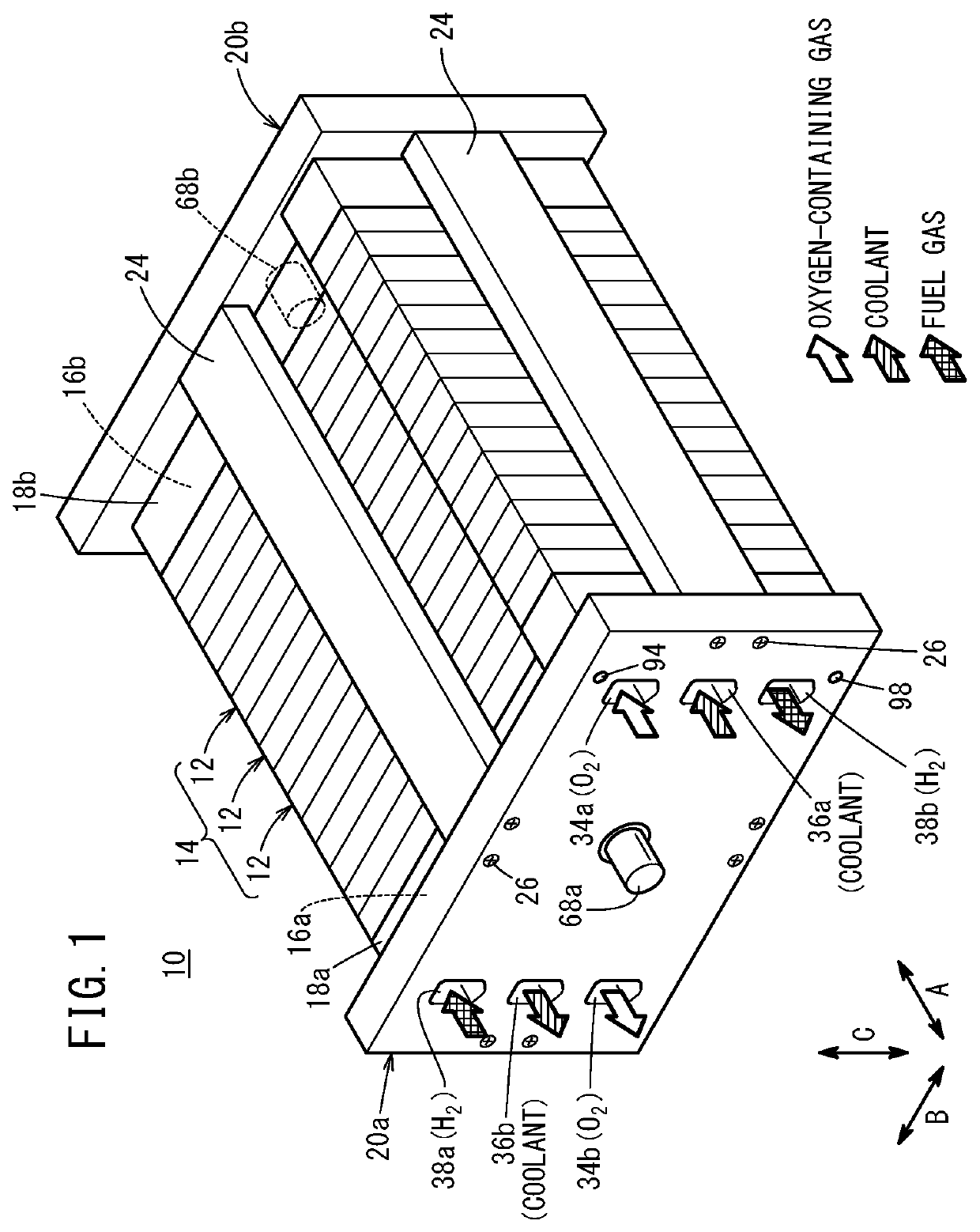
[0022]As shown in FIG. 1, a fuel cell stack 10 according to an embodiment of the present invention is equipped with a stack body 14 in which a plurality of power generation cells 12 each constituting a unit fuel cell are stacked in a horizontal direction (the direction of the arrow A or in a direction of gravity (the direction of the arrow C). The fuel cell stack 10, for example, is mounted in a non-illustrated fuel cell vehicle (fuel cell automotive vehicle).

[0023]A terminal plate 16a, an insulator 18a, and an end plate 20a are arranged in this order sequentially toward the outside on one end of the stack body 14 in the stacking direction (the direction of the arrow A). A terminal plate 16b, an insulator 18b, and an end plate 20b are arranged in this order sequentially toward the outside on another end of the stack body 14 in the stacking ...


PUM

PropertyMeasurementUnit
shapeaaaaaaaaaa
compressiveaaaaaaaaaa
thicknessaaaaaaaaaa

Abstract

A fuel cell separator (first and second separators) of a fuel cell stack is formed in a plate shape, and includes a passage bead (projection) configured to form a seal that prevents leakage of fluid. The passage bead is formed integrally with a surface of the separator in a manner so as to project from the surface, and when viewed in cross section, is formed in a multistage trapezoidal shape.

Description

CROSS-REFERENCE TO RELATED APPLICATION[0001]This application is based upon and claims the benefit of priority from Japanese Patent Application No. 2018-133002 filed on Jul. 13, 2018, the contents of which are incorporated herein by reference.BACKGROUND OF THE INVENTIONField of the Invention[0002]The present invention relates to a fuel cell separator and a fuel cell stack.Description of the Related Art[0003]A fuel cell stack is constituted by stacking together a plurality of power generation cells. Each of the power generation cells is equipped with a membrane electrode assembly (MEA) in which an anode, a solid polymer electrolyte membrane, and a cathode are stacked, and a pair of fuel cell separators in the form of bipolar plates that sandwich the MEA therebetween.[0004]For example, in U.S. Pat. No. 6,605,380, a pair of plates (fuel cell separators) are disclosed which are applied to a power generation cell. A bead which projects from a separator surface is formed on one of the fuel...

Claims


Application Information

Patent Timeline
Patent Type & Authority Applications(United States)
IPC IPC(8): H01M8/0247H01M8/0276H01M8/1004H01M8/0267H01M8/241
CPCH01M8/1004H01M8/0276H01M8/241H01M8/0247H01M8/0267H01M8/0273H01M8/0206H01M8/0208H01M8/0228H01M8/242Y02E60/50
Inventor OYAMA, SATOSHITOMANA, YU
Owner HONDA MOTOR CO LTD
Why Eureka
Try Eureka