
Transmission apparatus, transmission method, reception apparatus, and reception method

Active Publication Date: 2020-01-16
SATURN LICENSING LLC
View PDF0 Cites 4 Cited by
  • Summary
  • Abstract
  • Description
  • Claims
  • Application Information

AI Technical Summary

Benefits of technology

The technology described in this patent allows for moving image data to be transferred at both normal and high frames rates. This means that the data can be transferred without causing any issues or delays.

Problems solved by technology

However, the image captured with the high-speed frame shutter has an effect that moving blur is improved and image quality with high sharpness is realized while the image has an element that leads to a problem in a traditional frame inter-polation technology in terms of the image quality on a reception and reproduction side that displays the moving image sequence at a lower frame rate than the distributed high frame rate.
Therefore, the difference between both the cases is displayed as significant degradation in the image quality.
High load computation is necessary to improve accuracy of the motion vector search at the time of the frame interpolation, which affects receiver cost.

Method used


Image

  • Transmission apparatus, transmission method, reception apparatus, and reception method
  • Transmission apparatus, transmission method, reception apparatus, and reception method
  • Transmission apparatus, transmission method, reception apparatus, and reception method

Examples


embodiment

1. Embodiment

>

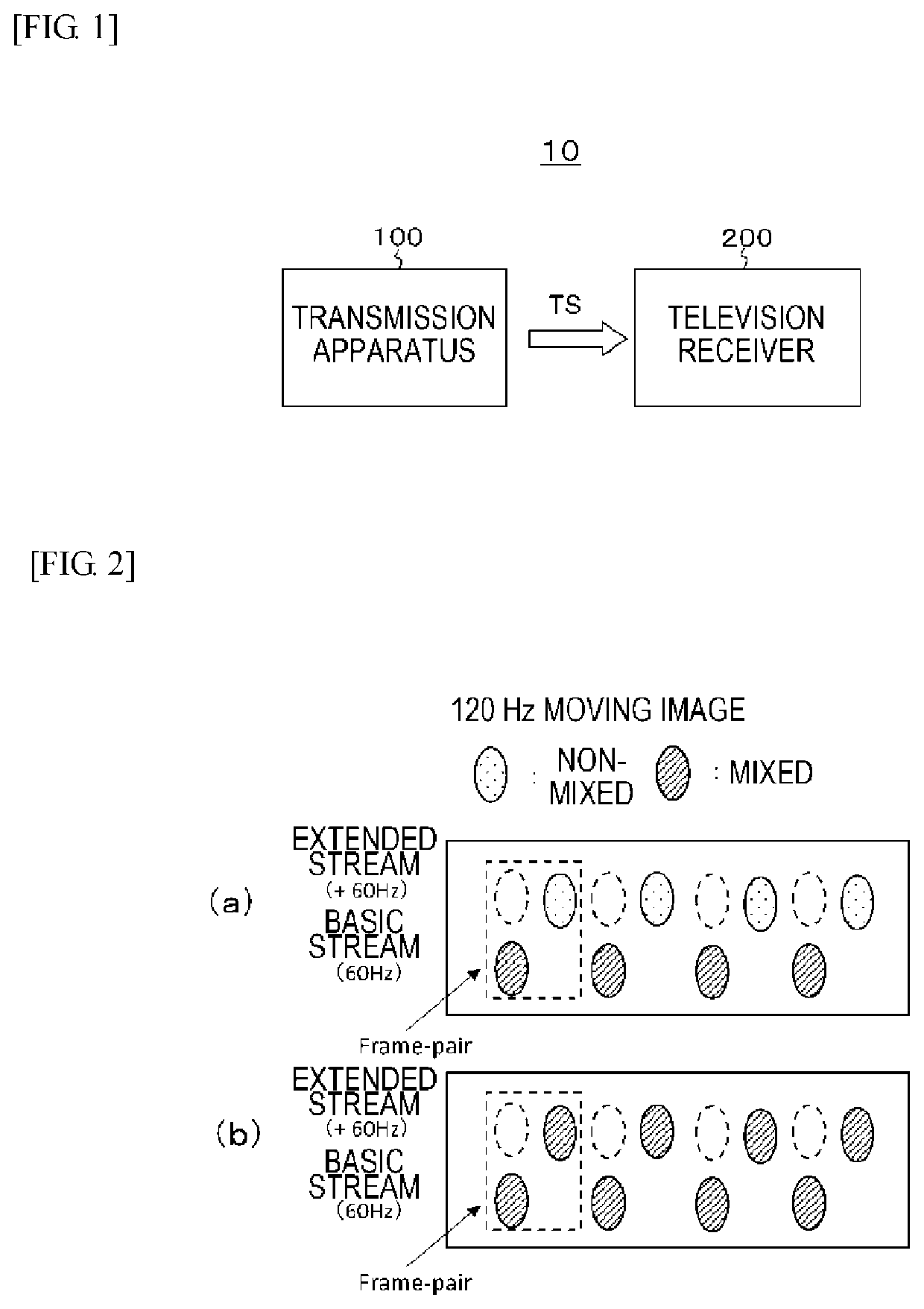
[0062]FIG. 1 illustrates a configuration example of a transmission and reception system 10 according to an embodiment. This transmission and reception system 10 has a transmission apparatus 100 and a television receiver 200.

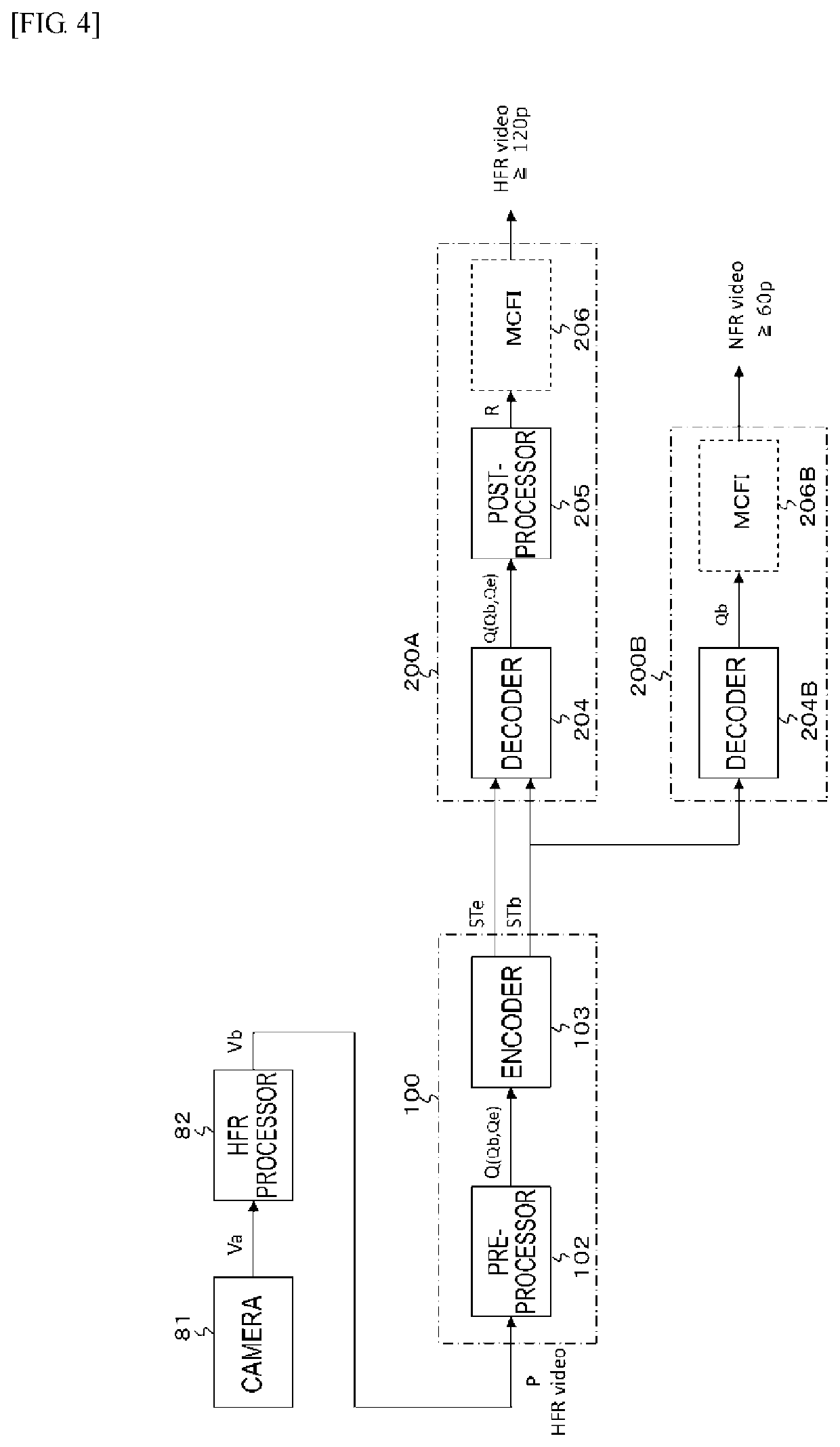
[0063]The transmission apparatus 100 transmits a transport stream TS as a container on a broadcasting wave. This transport stream TS includes a basic stream (basic video stream) obtained by processing moving image data at a high frame rate, that is, at 120 Hz or 240 Hz in this embodiment and an extended stream (extended video stream). In this embodiment, the basic stream and the extended stream have a NAL unit structure.

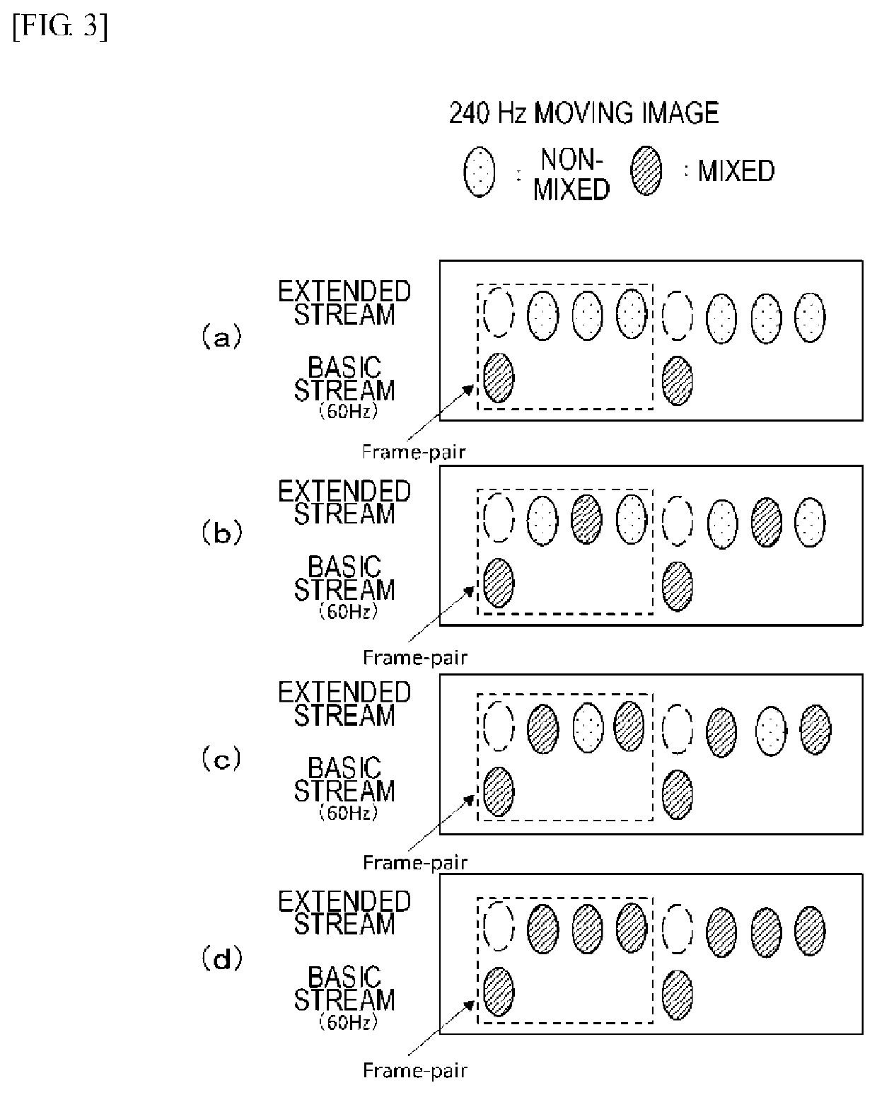
[0064]Here, the basic stream is obtained as follows. That is, moving image data at a high frame rate after mixing processing is obtained by performing processing of mixing, at a mixing rate independent for each frame, image data in peripheral frames with image data in each frame of the moving image data at the high frame rate before ...

modification example

2. Modification Example

[0163]In addition, although the example of the transmission and reception system 10 that includes the transmission apparatus 100 and the television receiver 200 has been described in the aforementioned embodiment, the configuration of the transmission and reception system to which the present technology can be applied is not limited thereto. A case is also considered in which a portion of the television receiver 200 includes a set top box and a display that are connected by a digital interface such as a high-definition multimedia interface (HDMI), for example. Note that {HDMI} is a registered trademark.

[0164]FIG. 21 illustrates a configuration example of a transmission and reception system 10A. This transmission and reception system 10A has a configuration having the transmission apparatus 100, a set top box (STB) 200-1, and a display 200-2. The set top box (STB) 200-1 and the display 200-2 are connected by the HDMI.

[0165]Since the transmission apparatus 100 i...


PUM


Abstract

There is provided a transmission apparatus including: a processing unit that performs processing of mixing, at a mixing rate independent for each frame, image data in peripheral frames with image data in each frame of first moving image data at a first frame rate and obtains second moving image data at the first frame rate. At least image data in a frame corresponding to a second frame rate that is lower than the first frame rate in the image data in each frame that forms the second moving image data is brought into a state in which the image data is mixed with the image data in the peripheral frames.

Description

CROSS REFERENCE TO RELATED APPLICATIONS[0001]This application claims the benefit of Japanese Priority Patent Application JP 2017-085730 filed Apr. 24, 2017, the entire contents of which are incorporated herein by reference.TECHNICAL FIELD[0002]The present technology relates to a transmission apparatus, a transmission method, a reception apparatus, and a reception method, and more particularly to a transmission apparatus that transits moving image data at a high frame rate and the like. Background Art[0003]In recent years, a camera that performs high frame rate imaging with a high-speed frame shutter is known. For example, a normal frame rate is 60 Hz, 50 Hz, or the like while the high frame rate is a frame rate that is several times, several tens of times, or further several hundreds of times as high as the normal frame rate.[0004]In a case in which a high frame rate service is performed, it is considered that moving image data captured by a camera with a high-speed frame shutter is...

Claims


Application Information

Patent Timeline
IPC IPC(8): H04N21/2343H04N21/236H04N21/2662H04N19/30H04N5/232
CPCH04N21/2662H04N19/30H04N5/23232H04N21/236H04N21/234381H04N21/2343H04N21/23605H04N21/2355H04N23/951
Inventor TSUKAGOSHI, IKUO
Owner SATURN LICENSING LLC
Learn More