Safety cabinet
a safe and cabinet technology, applied in the field of safe cabinets, can solve the problems of reducing the air speed of inflow air flow, the inability to supply clean air, and the tightness of the structure, so as to reduce the blow-off air speed and the air flow of inflow air
- Summary
- Abstract
- Description
- Claims
- Application Information
AI Technical Summary
Benefits of technology
Problems solved by technology
Method used
Image

Examples
example 1
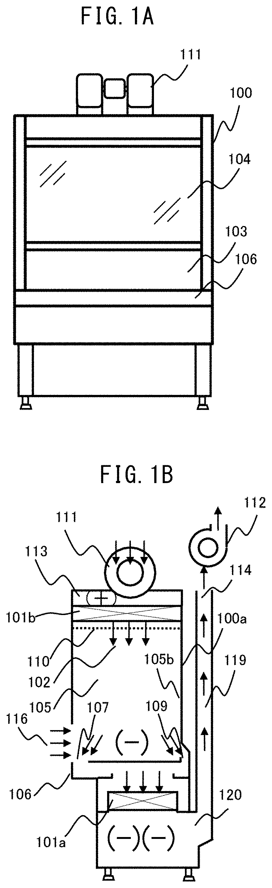
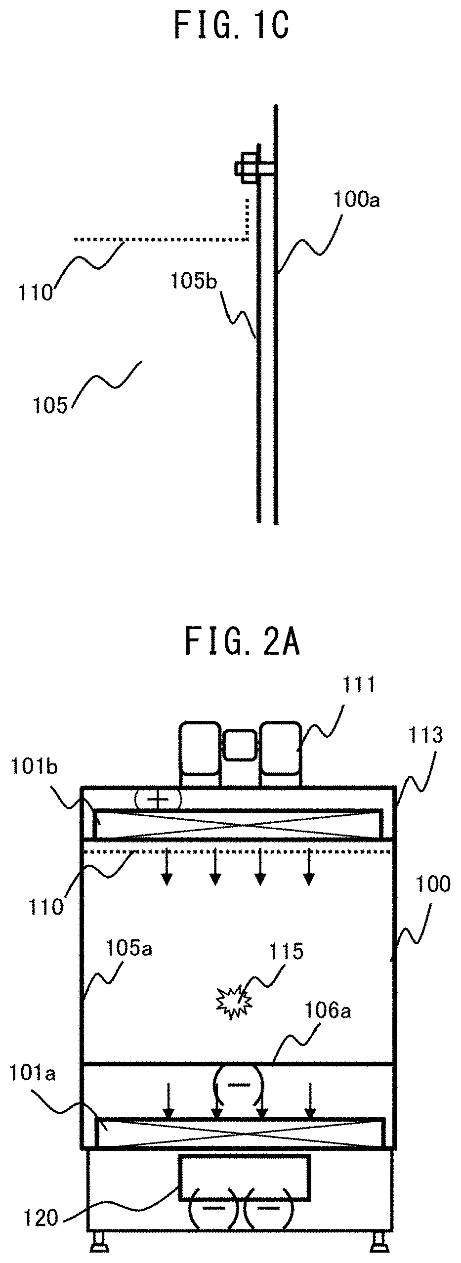
[0037]FIG. 1A is an example of an external front view illustrating the safety cabinet of Example 1, and FIG. 1B is an example of a side cross-sectional view. Moreover, FIG. 2A is an example of front sectional view which illustrates the safety cabinet of Example 1 at the time of work, and FIG. 2B is an example of side cross-sectional view.
[0038]A blow-off blower 111 sucks the air in a laboratory in which a safety cabinet 100 is disposed, and pressurizes a pressure chamber 113. Since the pressure chamber 113 is connected to a blow-off HEPA filter 101b, the air in the laboratory is purified by the blow-off HEPA filter 101b and blown out to a workspace 105 as clean air 102. The blow-off air speed of the clean air 102 blown into the workspace 105 is rectified by a flow straightening plate 110.
[0039]The front of the workspace 105 is surrounded by a front panel 104, the side surface thereof is surrounded by a workspace side wall surface 105a, the back surface thereof is surrounded by a wor...
example 2
[0054]FIG. 4A is an example of a front cross-sectional view illustrating the safety cabinet of Example 2, and FIG. 4B is an example of a side cross-sectional view.
[0055]In Example 2, the exhaust blower 112 is provided in the exhaust flow path 119 on the downstream of the exhaust HEPA filter 101a in Example 1. The safety cabinet of Class II Type B2 of the example is always used for outdoor exhaust. The clean air 102 blown out to the workspace 105 is blown out by the blow-off blower 111, and the inflow air flow 116 is generated by the suction air flow of the exhaust blower 112. The blow-off air speed of the clean air 102 depends on the capacity of the blow-off blower 111 in the safety cabinet 100. In Example 1, the inflow air flow 116 depends on the capacity of the exhaust blower 112 installed outside the safety cabinet 100, and in Example 2, the inflow air flow 116 depends on the exhaust blower 112 disposed in the exhaust flow path 119 of the safety cabinet 100. Therefore, in Example...
example 3
[0057]FIG. 5A is an example of a front cross-sectional view illustrating the safety cabinet of Example 3, and FIG. 5B is an example of a side cross-sectional view.
[0058]In Example 3, as in Example 1, an exhaust HEPA filter 101a is disposed below a work table 106. On the downstream side of the exhaust HEPA filter 101a, an exhaust blower 112 is disposed below the work table 106, and an exhaust flow path 119 is provided on the blow-off side of the exhaust blower 112. When the penetration ratio of the exhaust HEPA filter 101a is measured in Example 3, it is difficult to carry out a scanning test on the blow-off surface of the exhaust HEPA filter 101a as in other examples. In this case, it is necessary to evaluate the penetration ratio of 0.005% or less, by taking a place in which the air blown out from the exhaust HEPA filter 101a is well mixed together as a representative point. However, an exhaust blower suction port 124 which is a suction port of air of the exhaust blower 112 is a pl...
PUM
 Abstract
Description
Claims
Application Information
 - R&D
- Intellectual Property
- Life Sciences
- Materials
- Tech Scout
- Unparalleled Data Quality
- Higher Quality Content
- 60% Fewer Hallucinations
Browse by: Latest US Patents, China's latest patents, Technical Efficacy Thesaurus, Application Domain, Technology Topic, Popular Technical Reports.
© 2025 PatSnap. All rights reserved.Legal|Privacy policy|Modern Slavery Act Transparency Statement|Sitemap|About US| Contact US: help@patsnap.com