Automatic path generation device

Active Publication Date: 2020-01-23
FANUC LTD
View PDF0 Cites 4 Cited by
  • Summary
  • Abstract
  • Description
  • Claims
  • Application Information

AI Technical Summary

Benefits of technology

The present patent allows for a robot to automatically create a precise path for movement during welding.

Problems solved by technology

The temporary motion path is automatically generated by the motion planning algorithm and is not ideal as a motion path.

Method used


Image

  • Automatic path generation device
  • Automatic path generation device
  • Automatic path generation device

Examples


first embodiment

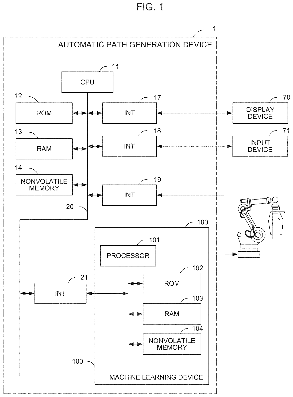
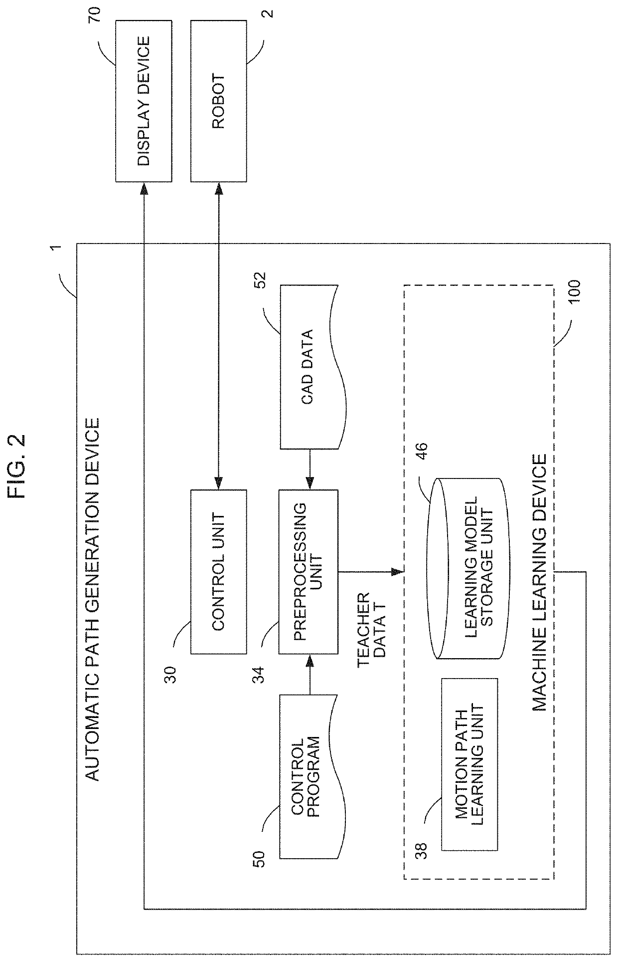
[0027]FIG. 2 is a schematic functional block diagram in the learning mode of the machine learning device 100 of the automatic path generation device 1 according to a The function of each functional block illustrated in FIG. 2 is realized by the CPU 11 of the automatic path generation device 1 illustrated in FIG. 1 and the processor 101 of the machine learning device 100 executing the respective system programs of the CPU 11 and the processor 101 and controlling the operation of each unit of the automatic path generation device 1 and the machine learning device 100.

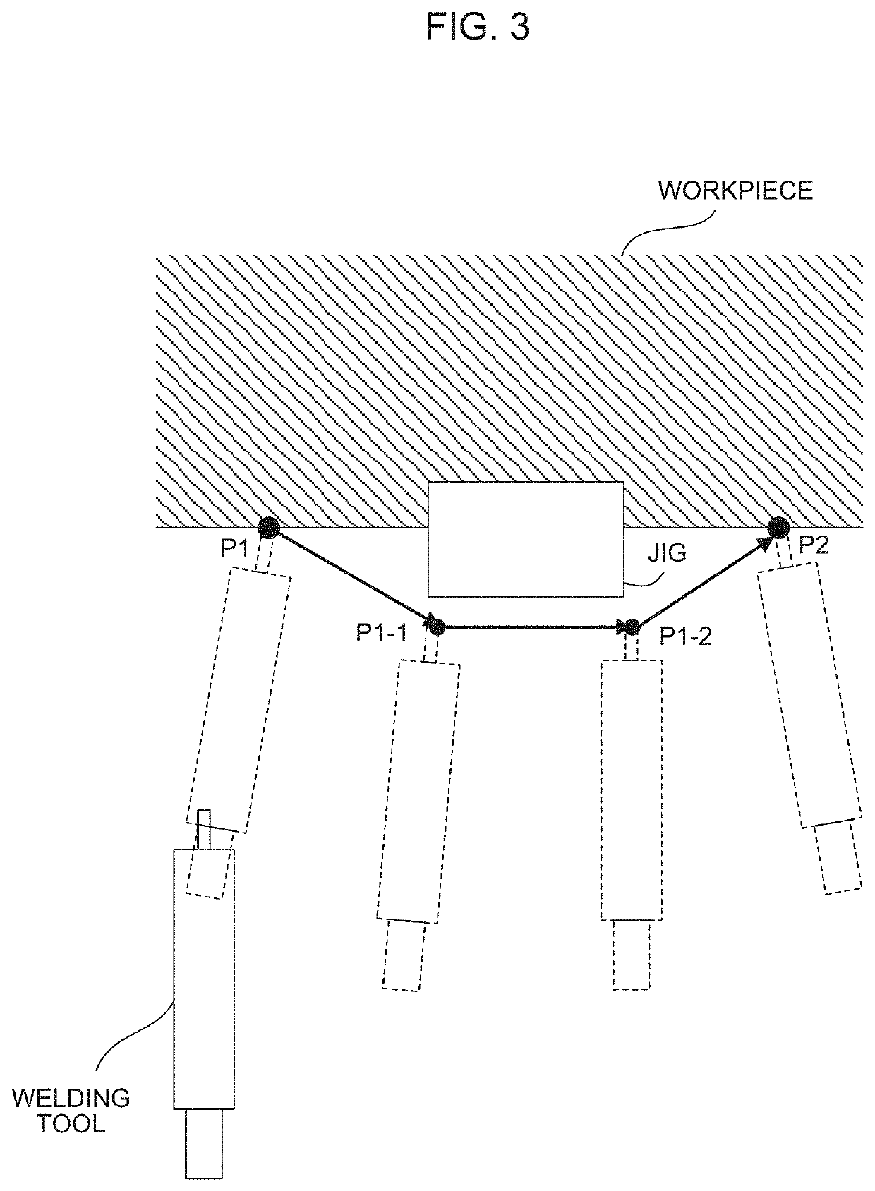
[0028]The automatic path generation device 1 includes a control unit 30, a preprocessing unit 34, and a motion path learning unit 38. The control unit 30 controls the robot 2. The preprocessing unit 34 creates teacher data used for the machine learning that is executed by the machine learning device 100. The teacher data is created based on a control program 50 including information indicating a motion path created by tea...

second embodiment

[0038]FIG. 7 is a schematic functional block diagram in the estimation mode of the machine learning device 100 of the automatic path generation device 1 according to a Each functional block illustrated in FIG. 7 is realized by the CPU 11 of the automatic path generation device 1 illustrated in FIG. 1 and the processor 101 of the machine learning device 100 executing the respective system programs of the CPU 11 and the processor 101 and controlling the operation of each unit of the automatic path generation device 1 and the machine learning device 100.

[0039]In the estimation mode, the automatic path generation device 1 of the present embodiment estimates the actual motion path based on the temporary motion path data 54. The automatic path generation device 1 controls the robot 2 based on the estimated actual motion path. The control unit 30 in the automatic path generation device 1 according to the present embodiment is similar in function to the control unit 30 in the automatic pat...

third embodiment

[0042]FIG. 8 is a schematic functional block diagram in the estimation mode of the machine learning device 100 of the automatic path generation device 1 according to a The function of each functional block illustrated in FIG. 8 is realized by the CPU 11 of the automatic path generation device 1 illustrated in FIG. 1 and the processor 101 of the machine learning device 100 executing the respective system programs of the CPU 11 and the processor 101 and controlling the operation of each unit of the automatic path generation device 1 and the machine learning device 100. The control program 50, the CAD data 52, the temporary motion path data 54, and the like are not illustrated in FIG. 8.

[0043]The automatic path generation device 1 of the present embodiment includes a simulation unit 42 simulating the motion of the robot 2. The simulation unit 42 performs the simulation using the actual motion path that the motion path estimation unit 40 estimates based on the temporary motion path dat...


PUM


Abstract

An automatic path generation device includes a preprocessing unit creating teacher data based on a temporary motion path which is a motion path between a plurality of motion points where a robot moves and which is automatically generated with a motion planning algorithm and an actual motion path which is a motion path between the motion points and which is created by a skilled worker and a motion path learning unit generating a learned model which has learned a difference between the temporary motion path and the actual motion path with teacher data created by the preprocessing unit.

Description

RELATED APPLICATIONS[0001]The present application claims priority to Japanese Patent Application Number 2018-134515 filed Jul. 17, 2018, the disclosure of which is hereby incorporated by reference herein in its entirety.BACKGROUND OF THE INVENTION1. Field of the Invention[0002]The present disclosure relates to an automatic path generation device.2. Description of the Related Art[0003]The motion path at a time when a robot performing spot welding or arc welding moves (time series data indicating, for example, the coordinate value and the velocity of each axis of the robot determining a welding tool position or a welding tool posture) is generated by teaching from a worker. In some cases, the robot's motion path is automatically generated by a motion planning algorithm such as a rapidly exploring random tree (RRT) and based on given data indicating a hit point position on a workpiece and workpiece or jig shape data given as CAD data (for example, Re-publication of PCT International Pu...

Claims


Application Information

Patent Timeline
IPC IPC(8): B25J9/16G05B19/425
CPCB25J9/1664G05B19/425B25J9/163G05B2219/40477
Inventor KATO, SEIGONAGATSUKA, YOSHIHARUKIMOTO, YUUKI
Owner FANUC LTD
Why Eureka
Try Eureka