
Permanent magnet three phase machine for high speed applications having low vibration and low resistive losses

a permanent magnet, three-phase technology, applied in the direction of rotating magnets, synchronous machines with stationary armatures, dynamo-electric machines, etc., can solve the problem of insignificant resultant impedance increase, and achieve the effect of minimizing the volume of coil wires, minimizing the magnitude of reluctance torque, and maximizing the frequency per revolution

Inactive Publication Date: 2020-01-23
KONINKLJIJKE PHILIPS NV
View PDF0 Cites 2 Cited by
  • Summary
  • Abstract
  • Description
  • Claims
  • Application Information

AI Technical Summary

Benefits of technology

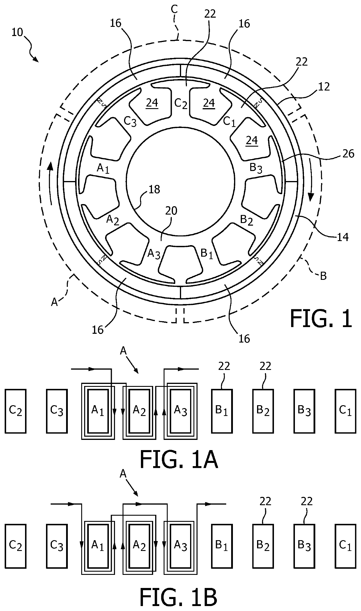
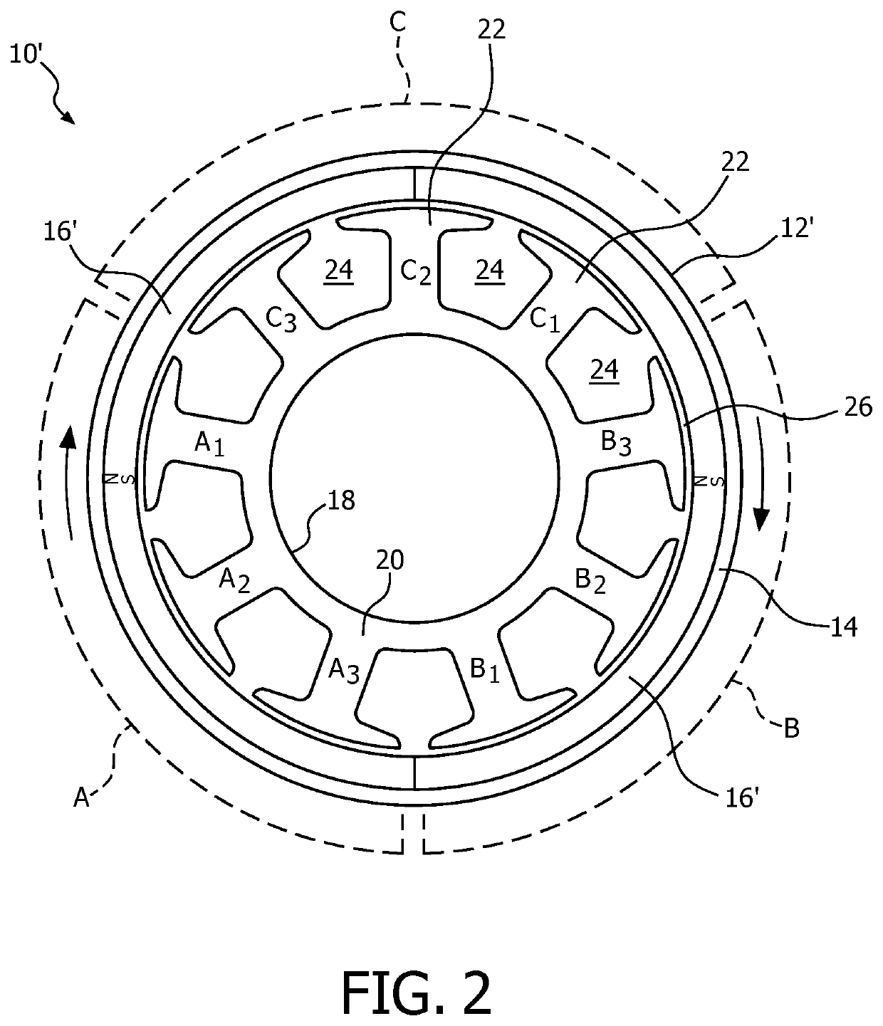
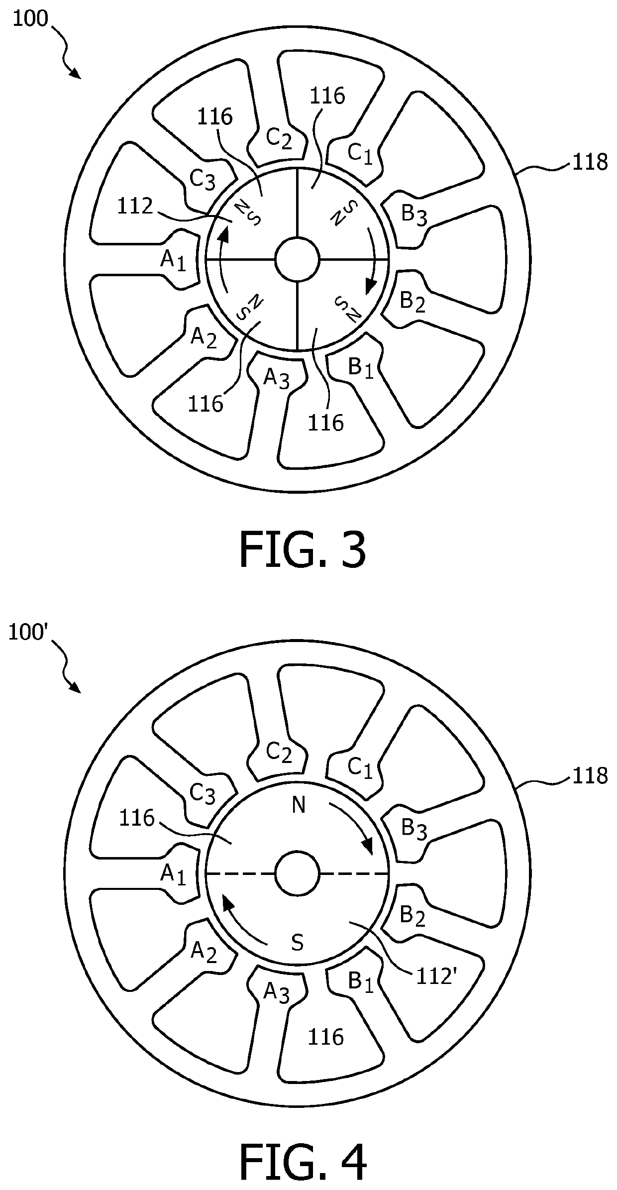
The present invention is a technical solution for a three-phase permanent magnet rotary machine that meets all the competing objectives of the machine. The machine has an armature and a permanent magnet assembly rotating relative to each other. The armature has ferromagnetic poles and slots, and the permanent magnet assembly has magnetic poles. This structure minimizes the reluctance torque and maximizes the frequency per revolution. The coils of each phase are placed in a limited sector of the armature so that they do not overlap each other. This reduces electromagnetic torque ripple and increases starting torque per unit volume of wire. The result is a compact, efficient machine with high energy efficiency and torque.

Problems solved by technology

Although close placement of coils of alternating polarity increases the self-inductance of each phase, the resultant increase in impedance is insignificant except at unusually high motor speeds.

Method used


Image

  • Permanent magnet three phase machine for high speed applications having low vibration and low resistive losses
  • Permanent magnet three phase machine for high speed applications having low vibration and low resistive losses
  • Permanent magnet three phase machine for high speed applications having low vibration and low resistive losses

Examples


Embodiment Construction

[0023]As used herein, the singular form of “a”, “an”, and “the” include plural references unless the context clearly dictates otherwise. As used herein, the statement that two or more parts or components are “coupled” shall mean that the parts are joined or operate together either directly or indirectly, i.e., through one or more intermediate parts or components, so long as a link occurs. As used herein, “directly coupled” means that two elements are directly in contact with each other. As used herein, “fixedly coupled” or “fixed” means that two components are coupled so as to move as one while maintaining a constant orientation relative to each other.

[0024]As used herein, the word “unitary” means a component is created as a single piece or unit. That is, a component that includes pieces that are created separately and then coupled together as a unit is not a “unitary” component or body. As employed herein, the statement that two or more parts or components “engage” one another shal...


PUM


Abstract

A compact three-phase permanent magnet rotary machine having minimal reluctance torque and electromagnetic torque ripple, and maximum energy efficiency and starting torque per unit volume of winding, comprises an armature having 3(2n+1) ferromagnetic poles and slots, where n is an integer of 1 or more, and a permanent magnet assembly having either 2, 4 or 6 permanent magnet poles. Each of the three phases of the winding comprises multiple coils, each wound about a respective ferromagnetic pole and occupying a pair of slots located immediately on each side of a respective pole. The coils of a particular phase are located within a sector of the circular array of ferromagnetic poles encompassing 2n+1 poles.

Description

BACKGROUND OF THE INVENTION1. Field of the Invention[0001]The present invention relates to improvements in three-phase permanent magnet rotary electrical machines such as motors and generators. More particularly, the invention relates to such improvements which minimize reluctance torque and electromagnetic torque ripple while maximizing compactness, energy efficiency, motor starting torque per unit volume of winding, and operating speed. The invention also relates to such improvements which move the 1st and subsequent harmonics of reluctance torque and electromagnetic ripple from a lower frequency range to a higher frequency range which may be less likely heard and felt by a human.2. Description of the Related Art[0002]Permanent magnet motors having slotted armatures and multi-coil phases have been produced in the past utilizing an odd number of slots and armature poles and an even number of permanent magnet poles to reduce reluctance torque and thus vibration, as exemplified by th...

Claims


Application Information

Patent Timeline
Patent Type & Authority Applications(United States)
IPC IPC(8): H02K29/03H02K21/22H02K3/28
CPCH02K21/22H02K3/28H02K29/03H02K21/00
Inventor NORRIS, RUSSELL HUGHES
Owner KONINKLJIJKE PHILIPS NV
Learn More