Systems and methods for autonomous machine tracking and localization of mobile objects

a technology of mobile objects and tracking systems, applied in the field of object tracking, can solve the problems of complex challenges involving a plethora, conventional tracking systems are almost always limited to tracking, and the fundamental limitations of machine vision systems

Active Publication Date: 2020-01-30
TG 17 LLC
View PDF0 Cites 14 Cited by
  • Summary
  • Abstract
  • Description
  • Claims
  • Application Information

AI Technical Summary

Benefits of technology

[0017]In a still further aspect, the method further comprises calculating correction values to minimize random errors and drift in the IMU measurements, the correction values based at least in part on one or more of the optical triangulation and the current location coordinate of the drone.

Problems solved by technology

While the problem of object tracking can appear deceptively simple on its surface, it in reality poses a complex challenge involving a plethora of different variables and environmental factors that must be accounted for.
Conventional tracking systems are almost always limited to tracking only certain types of targets or targets with suitable characteristics, e.g. targets of a certain size, targets of a certain material composition, or targets having some other property to which the tracking system is attuned.
In theory, these machine vision systems are fundamentally limited by the sensing resolution or resolving power of their vision sensors.
In practice, however, these systems are limited by the enormous computational power required to detect certain types and classes of objects well before they are limited by their sensing resolution.
Indeed, such systems struggle with real-time tracking of relatively small or fast moving objects and are plagued with high sensitivities to adverse environmental conditions, e.g. snow, fog, and other conditions of low light, low visibility, and / or low contrast.
Additionally, these conventional machine vision systems require maintaining line of sight (LOS) with the target or targets being tracked, which limits their utility in the likely event that LOS is lost with the target.
This likelihood is exacerbated by the fact that conventional machine vision systems are often bulky and generally not portable if processing is performed locally, and if processing is performed remotely (e.g. in the cloud or at a remote server), conventional machine visions systems are often underpowered, subject to high latency, and vulnerable to network interruption.

Method used


Image

  • Systems and methods for autonomous machine tracking and localization of mobile objects
  • Systems and methods for autonomous machine tracking and localization of mobile objects
  • Systems and methods for autonomous machine tracking and localization of mobile objects

Examples


Embodiment Construction

[0033]Various embodiments of the disclosure are discussed in detail below. While specific implementations are discussed, it should be understood that this is done for illustration purposes only. A person skilled in the relevant art will recognize that other components and configurations may be used without parting from the spirit and scope of the disclosure. Additional features and advantages of the disclosure will be set forth in the description which follows, and in part will be obvious from the description, or can be learned by practice of the herein disclosed principles. It will be appreciated that for simplicity and clarity of illustration, where appropriate, reference numerals have been repeated among the different figures to indicate corresponding or analogous elements. The description is not to be considered as limiting the scope of the embodiments described herein.

SUMMARY / OVERVIEW

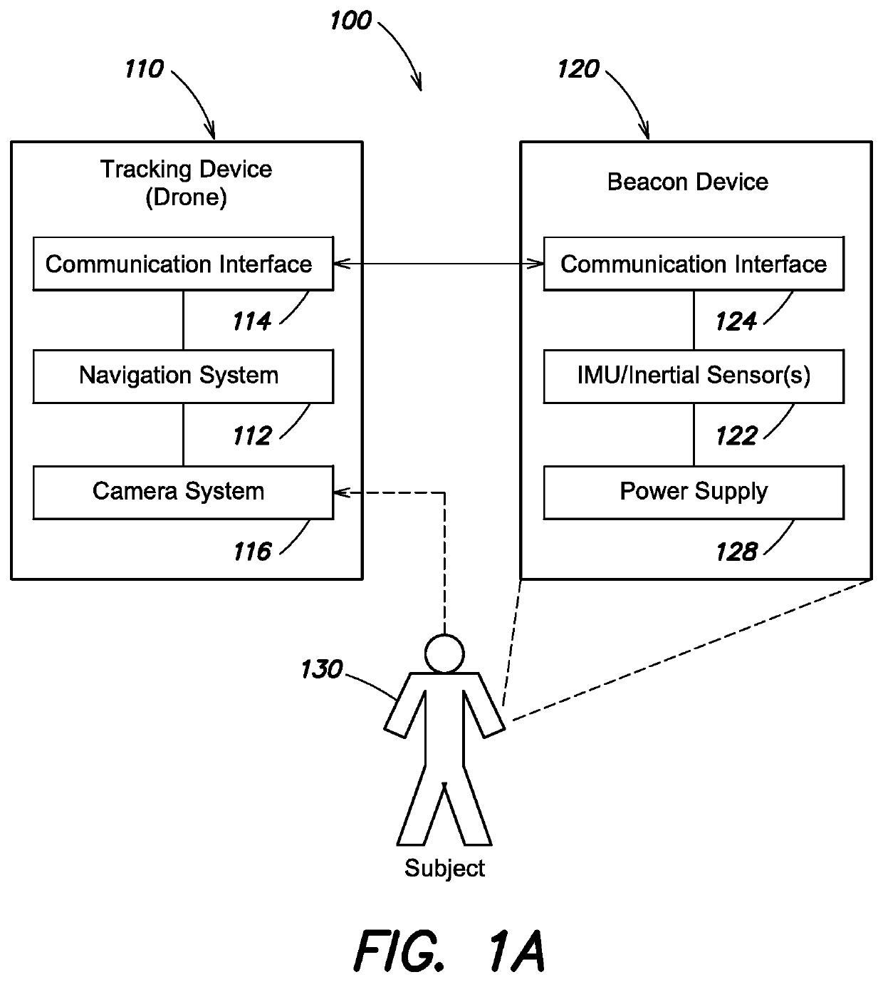
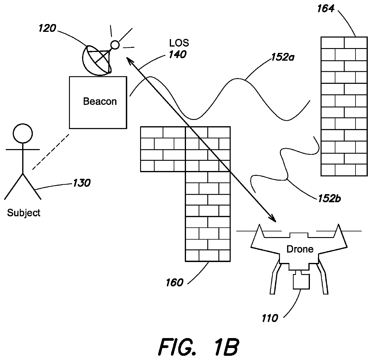
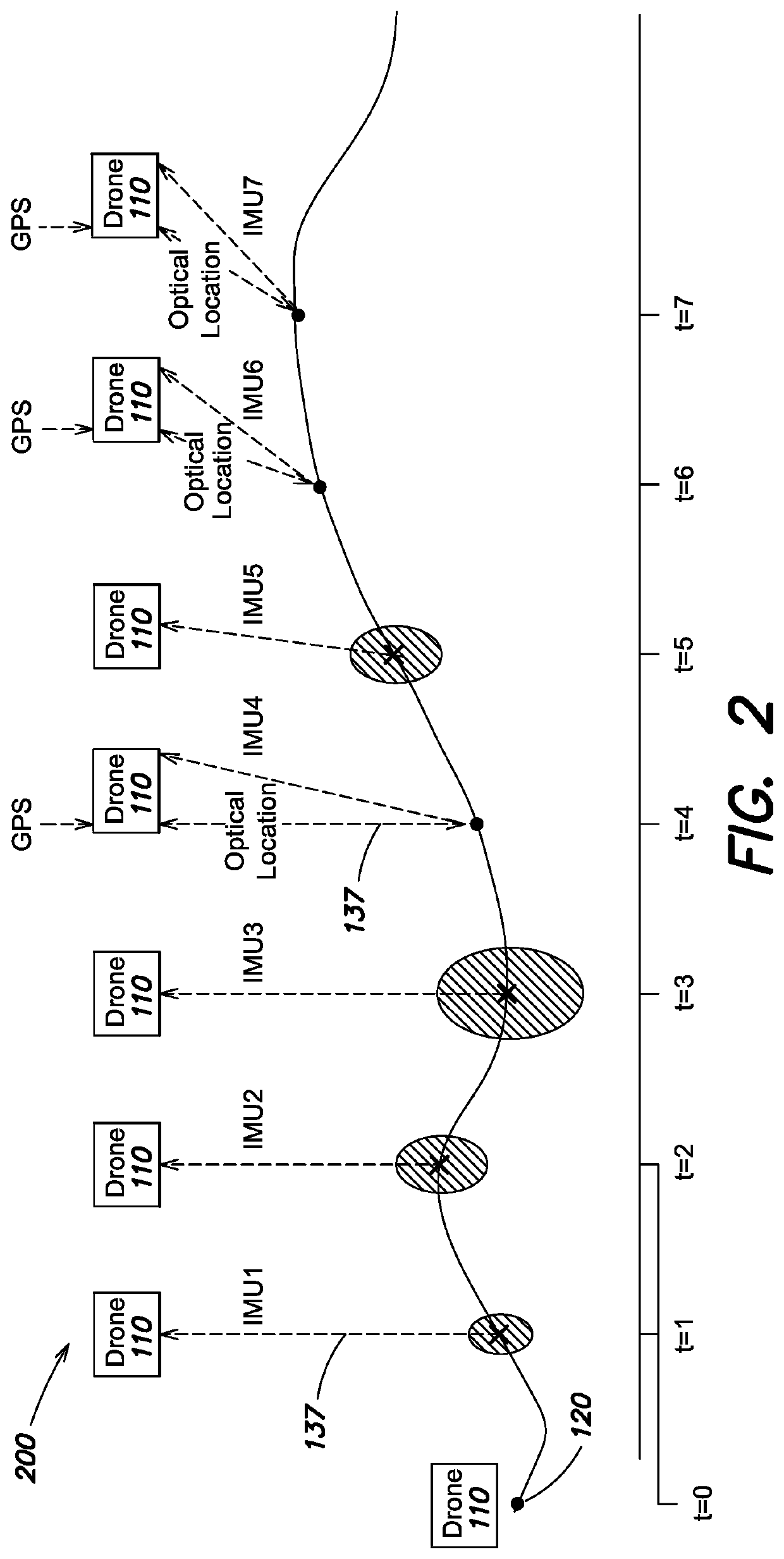
[0034]Disclosed are systems and methods for autonomous tracking and localization of moving obje...


PUM


Abstract

Disclosed are technologies for autonomous tracking. An initial coordinate of a beacon device carried by a user is registered as a dead reckoning waypoint with a drone configured to track the user. The drone receives IMU measurements from the beacon as the user moves. For each IMU measurement, a displacement vector characterizing user movement is calculated. Estimated beacon locations are calculated by dead reckoning, based on the displacement vectors and the dead reckoning waypoint. Later, an updated dead reckoning waypoint is calculated by obtaining the current location coordinate of the drone and performing optical triangulation to determine a relative position of the user with respect to the drone. The updated dead reckoning waypoint does not depend on previously estimated beacon locations, and accumulated IMU/estimation error is eliminated. Tracking continues, where subsequent estimated locations of the beacon are calculated by dead reckoning based on the updated dead reckoning waypoint.

Description

CROSS-REFERENCE TO RELATED APPLICATIONS[0001]This application claims the benefit of priority to U.S. Provisional Application No. 62 / 702,489 filed Jul. 24, 2018 and entitled “SYSTEMS AND METHODS FOR AUTONOMOUS MACHINE TRACKING AND LOCALIZATION OF MOBILE OBJECTS,” the disclosure of which is herein incorporated by reference in its entirety.TECHNICAL FIELD[0002]The present disclosure pertains to object tracking, and more specifically to a system and method for tracking one or more moving objects with an autonomous machine.BACKGROUND[0003]While the problem of object tracking can appear deceptively simple on its surface, it in reality poses a complex challenge involving a plethora of different variables and environmental factors that must be accounted for. Conventional tracking systems are almost always limited to tracking only certain types of targets or targets with suitable characteristics, e.g. targets of a certain size, targets of a certain material composition, or targets having som...

Claims


Application Information

Patent Timeline
Patent Type & Authority Applications(United States)
IPC IPC(8): G01C21/16G01C21/20B64C39/02
CPCG01C21/20G01C21/165B64C2201/145B64C39/02G05D1/0094G01C21/1656B64U2201/104
Inventor BARATZ, ZCHARIAASHER, RONKESHET, JOSEPHFISHER, ITALY
Owner TG 17 LLC
Why Eureka
Try Eureka