
Turbine blade having an improved structure

a technology of turbine blades and blades, which is applied in the direction of blade accessories, engines/engines, engine fuctions, etc., can solve the problems of limiting the life of the blades, affecting the mechanical strength of the blade, and generating a large temperature difference between the outer walls of the blades

Active Publication Date: 2020-02-06
SAFRAN
View PDF0 Cites 0 Cited by
  • Summary
  • Abstract
  • Description
  • Claims
  • Application Information

AI Technical Summary

Benefits of technology

The present invention relates to a new design for high pressure aviation gas turbine blades that can withstand higher temperatures and improve engine performance. The invention addresses the problem of cooling circuits in these blades, which can induce dilations and forces that can endanger the mechanical strength of the blades and impact their lifetime. The invention proposes a new design with reinforcing beams placed inside the inner cavities of the blades to improve their strength and allow for optimized cooling. The technical effects of the invention include improved cooling efficiency, reduced temperature differences between the blade walls, and improved engine performance.

Problems solved by technology

These temperatures reach values which are considerably higher than those which the different parts which are in contact with these gases can endure without damage, which has the consequence of limiting their lifetime.
Advanced circuits of this type have the disadvantage of generating a large difference in temperature between the outer walls of the blade in contact with the stream and the walls in the core of the blade.
These large differences in temperature induce dilations and forces which can endanger the mechanical strength of the blade during operation and thus impact its lifetime.
The dilations of the walls in the orthoradial plane generate, in particular, forces around the junction zones between the core of the blade and the walls of the blade, which can cause a break.
It is well understood, however, that this penalizes the general performance of the blade.

Method used


Image

  • Turbine blade having an improved structure
  • Turbine blade having an improved structure
  • Turbine blade having an improved structure

Examples


Embodiment Construction

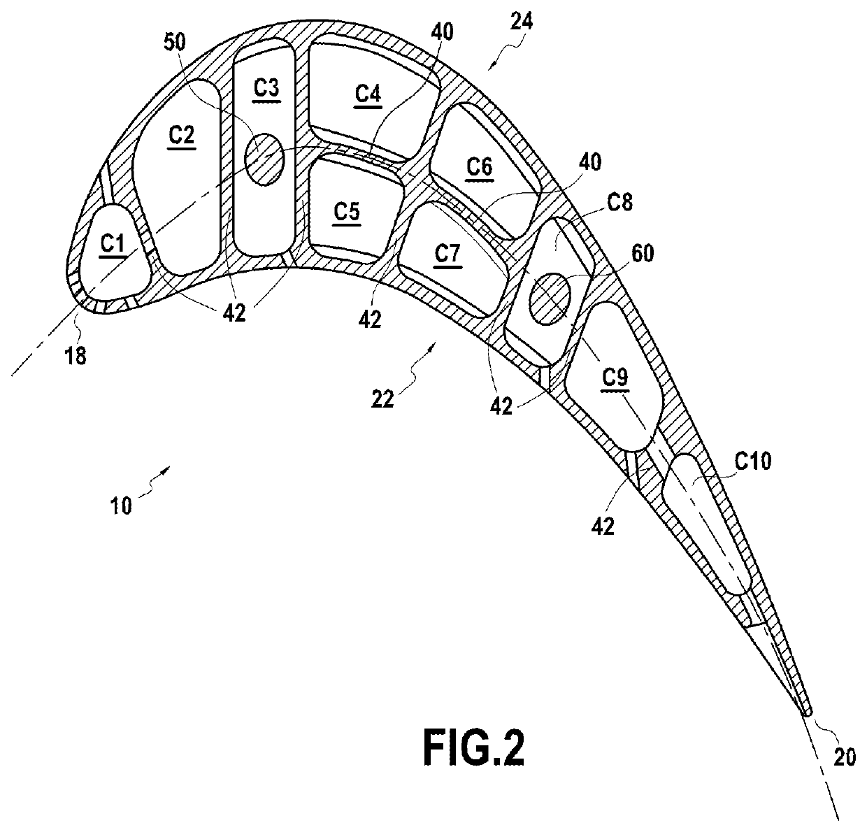
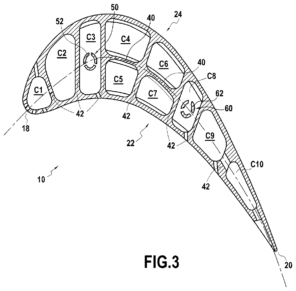
[0020]The invention is described hereafter with reference to FIGS. 1 to 3.

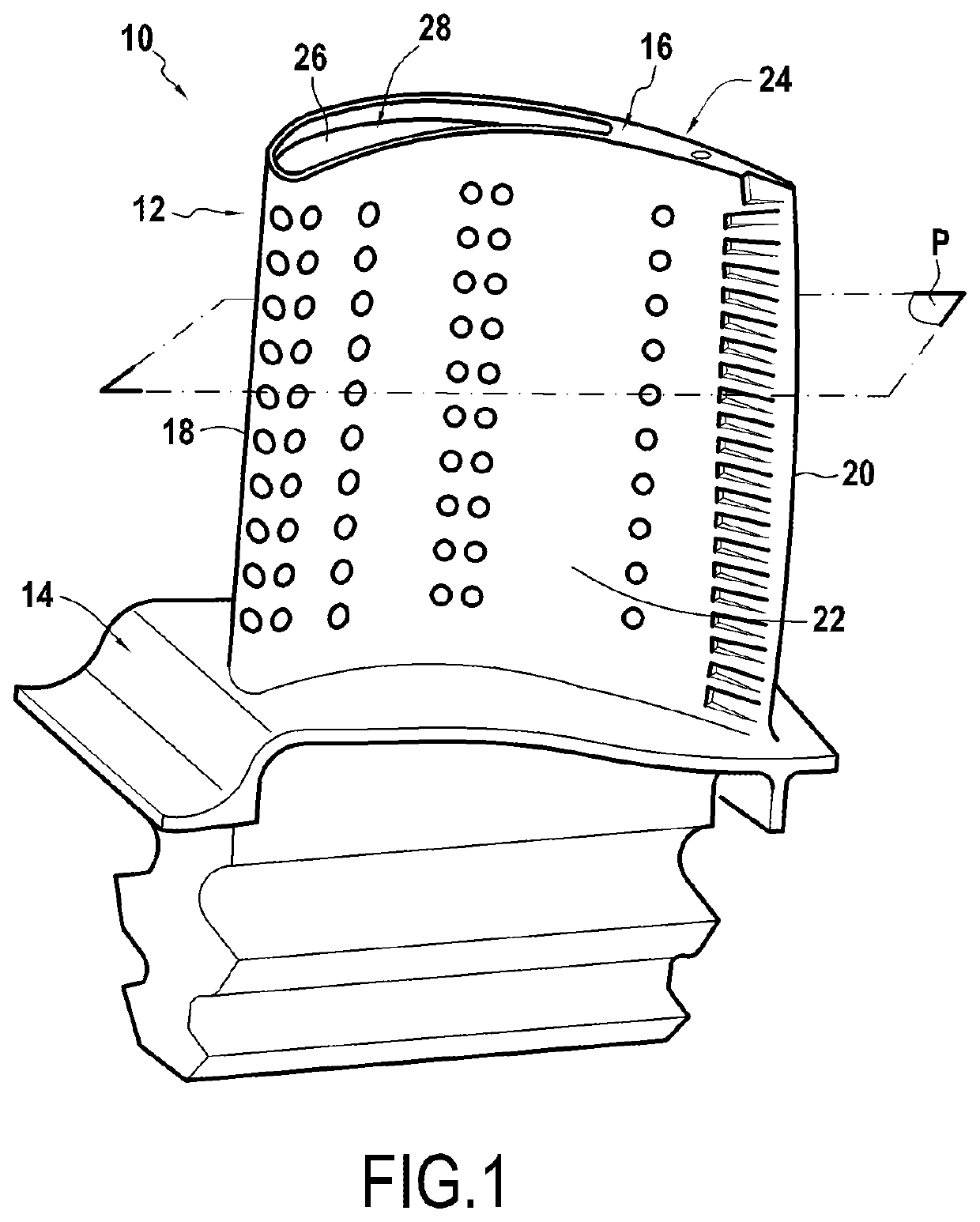
[0021]FIG. 1 illustrates a movable blade 10, metal for example, of a turbine engine high pressure turbine. Of course, the present invention can also apply to other movable or fixed blades of the turbine engine.

[0022]The blade 10 includes an aerodynamic surface 12 (or airfoil) which extends radially between a blade root 14 and a blade tip 16.

[0023]The blade root 14 is adapted to be mounted on a rotor disk of the high pressure turbine, the blade tip 16 being radially opposite the blade root 14.

[0024]The aerodynamic surface 12 has four distinct zones: a leading edge 18 disposed facing the flow of hot gases originating in the combustion chamber of the turbine engine, a trailing edge 20 opposite to the leading edge 18, a lower surface wall 22 and an upper surface wall 24, these lower 22 and upper 24 walls connecting the leading edge 18 to the trailing edge 20.

[0025]At the blade tip 16, the aerodynamic surface 12 of...


PUM


Abstract

Aviation turbine blade (10) extending in the radial direction from a blade root (14) as far as an upper partition wall (26), said blade (10) comprising a plurality of inner cavities (C1-C10) defining at least one cooling circuit, each of said inner cavities (C1-C10) being defined by walls among inner walls (40, 42), a lower surface wall (22), an upper surface wall (24), the blade root (14) and the upper partition wall (26), said blade (10) being characterized in that it comprises at least one reinforcing beam (50, 60) disposed inside one of the inner cavities (C3, C8), and connecting the blade root (14) to the upper partition wall (26), said reinforcing beam (50, 60) is not connected to the inner walls (40, 42), the lower surface wall (22) and the upper surface wall (24).

Description

FIELD OF THE INVENTION[0001]The present invention relates to the field of high pressure aviation gas turbine blades, more particularly to the inner structure of these blades, and a gas turbine including blades of this type.STATE OF THE PRIOR ART[0002]The movable blades of a gas turbine of an airplane engine, and particularly of the high pressure turbine, are subjected to the very high temperatures of the combustion gases during the operation of the engine. These temperatures reach values which are considerably higher than those which the different parts which are in contact with these gases can endure without damage, which has the consequence of limiting their lifetime.[0003]Moreover, an increase in the temperature of the high pressure turbine gasses allows an improvement in the efficiency of an engine, hence the ratio between the thrust of the engine and the weight of an airplane propelled by this engine. Consequently, efforts are made in order to achieve turbine blades which can r...

Claims


Application Information

Patent Timeline
Patent Type & Authority Applications(United States)
IPC IPC(8): F01D5/14F01D5/08
CPCF05D2260/2212F01D5/182F01D5/087F05D2260/202F01D5/188F01D5/147F01D5/189
Inventor PAQUIN, SYLVAINCARIOU, ROMAIN PIERREFLAMME, THOMAS MICHELROLLINGER, ADRIEN BERNARD VINCENT
Owner SAFRAN
Learn More