

Module
- Summary
- Abstract
- Description
- Claims
- Application Information
AI Technical Summary
Benefits of technology
Problems solved by technology
Method used
Image

Examples
first embodiment
Configuration
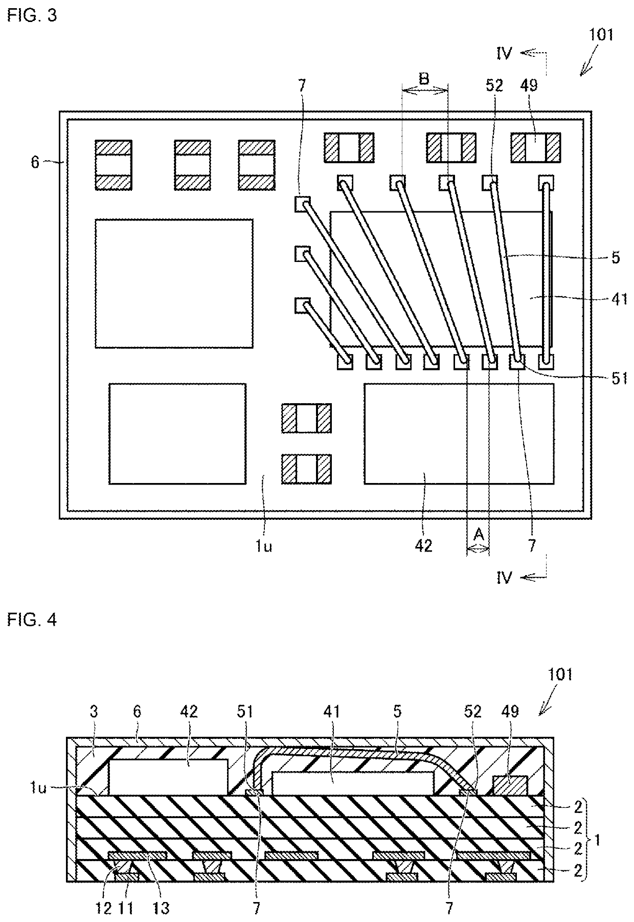
[0029]A module according to a first embodiment of the present disclosure will be described below with reference to FIG. 1 to FIG. 4. The module described herein may be a module with built-in components or a module with mounted components.
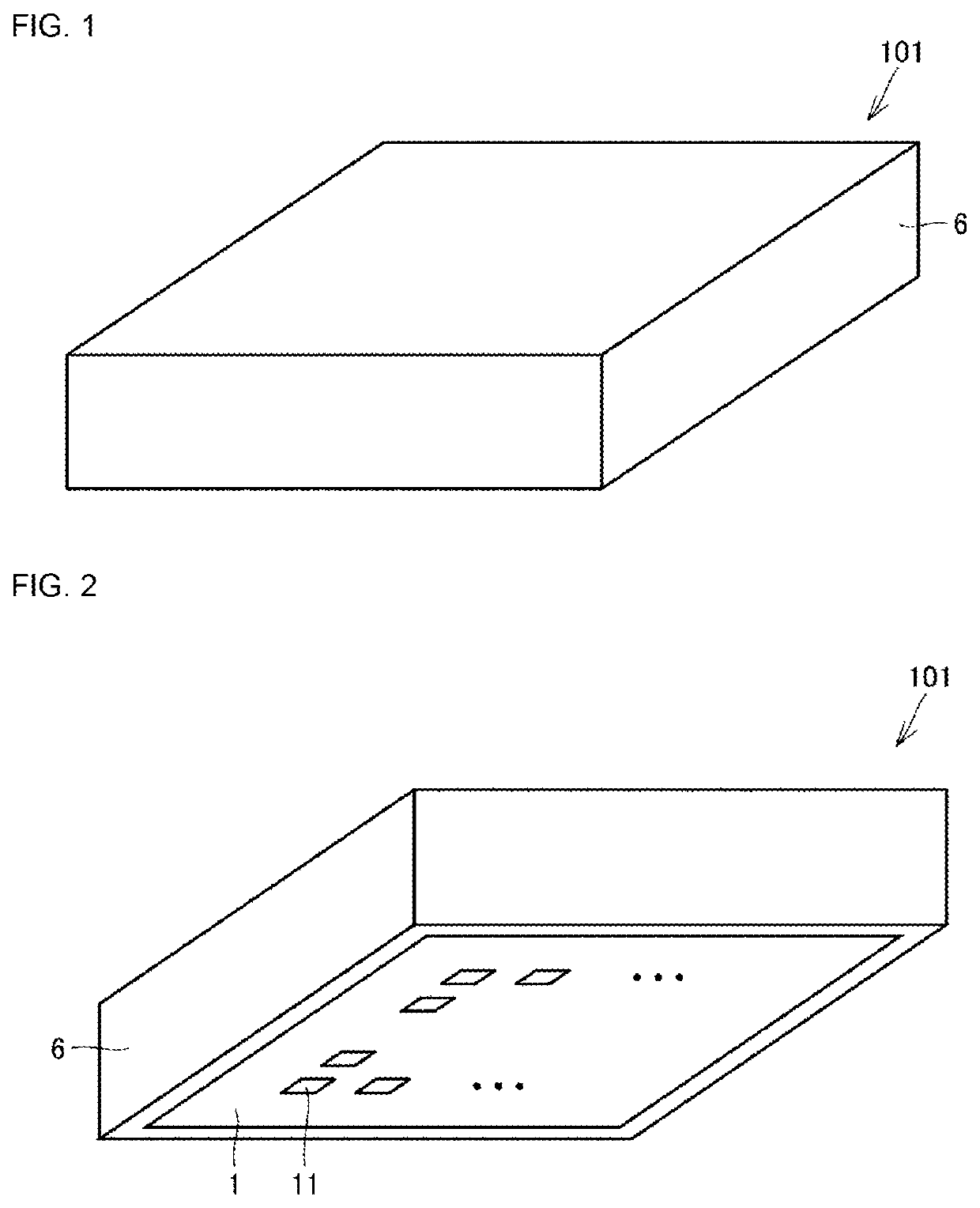
[0030]FIG. 1 illustrates an appearance of a module 101 according to the present embodiment. An upper surface and a side surface of the module 101 are covered with a shield film 6. FIG. 2 illustrates the module 101 when viewed from an angle at a lower side in FIG. 1. A lower surface of the module 101 is not covered with the shield film 6, and a substrate 1 is exposed. One or more external connection electrodes 11 are provided on a lower surface of the substrate 1. The number, the size and the arrangement of the external connection electrodes 11 illustrated in FIG. 2 are merely examples. The substrate 1 may be provided with a wiring on a surface or inside thereof. The substrate 1 may be a resin substrate or a ceramic substrate. The substr...
second embodiment
Configuration
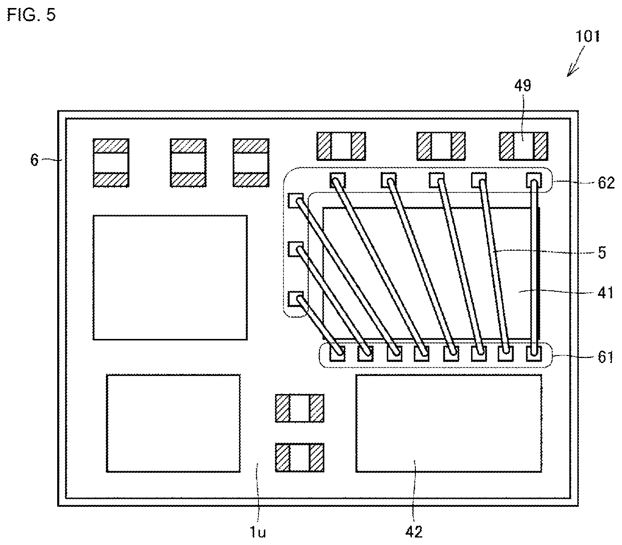
[0043]A module according to a second embodiment of the present disclosure will be described with reference to FIG. 6. FIG. 6 illustrates a module 102 according to the present embodiment in perspective plan view. The module 102 in this embodiment has the same basic configuration as that of the module 101 described in the first embodiment, but is different in the following points.
[0044]The module 102 includes a pad electrode 7a in addition to the pad electrode 7. The pad electrode 7 is connected to one first end 51 or one second end 52. The plurality of first ends 51 is connected to the pad electrode 7a.
[0045]In this embodiment, the integrating pad electrode 7a to which two or more of the first ends 51 are collectively connected is arranged in the first region 61.
Operation / Effects
[0046]In this embodiment, since there is provided the integrating pad electrode 7a to which two or more of the first ends 51 are collectively connected, a portion using the integrating pad elect...
third embodiment
Configuration
[0049]A module according to a third embodiment of the present disclosure will be described below with reference to FIG. 9 to FIG. 10. FIG. 9 illustrates a module 105 according to the present embodiment in perspective plan view. A region is clearly illustrated in FIG. 10. The module 105 in this embodiment has the same basic configuration as that of the module 101 described in the first embodiment, but is different in the following points.
[0050]In the module 105, the first component 41 is surrounded by at least a part of an aggregate of the first ends 51 and the second ends 52 of the two or more wires 5. That is, two or more wires 5 are arranged over the entire circumference of the first component 41 so as to straddle the first component 41. As illustrated in FIG. 10, the first region 61 in which the first ends 51 are arrayed may be substantially L-shaped. In the example illustrated in FIG. 10, the second region 62 in which the second ends 52 are arrayed is also substanti...
PUM
 Abstract
Description
Claims
Application Information