Electric vehicle charging system for existing infrastructure

Inactive Publication Date: 2020-02-20
ZAPTEC IP
View PDF0 Cites 7 Cited by
  • Summary
  • Abstract
  • Description
  • Claims
  • Application Information

AI Technical Summary

Benefits of technology

[0010]An object of the invention to provide scalable, compact and highly secure charging system for electricity-powered vehicles (EV) w

Problems solved by technology

The rapid increase in electricity-powered vehicles create however challenges, especially in urban locations such as inner cities.
For examples, setting up new charging stations is an expensive exercise, requiring earthwork for cabling and purchase of extensive new infrastructure.
The need of

Method used


Image

  • Electric vehicle charging system for existing infrastructure
  • Electric vehicle charging system for existing infrastructure
  • Electric vehicle charging system for existing infrastructure

Examples


Embodiment Construction

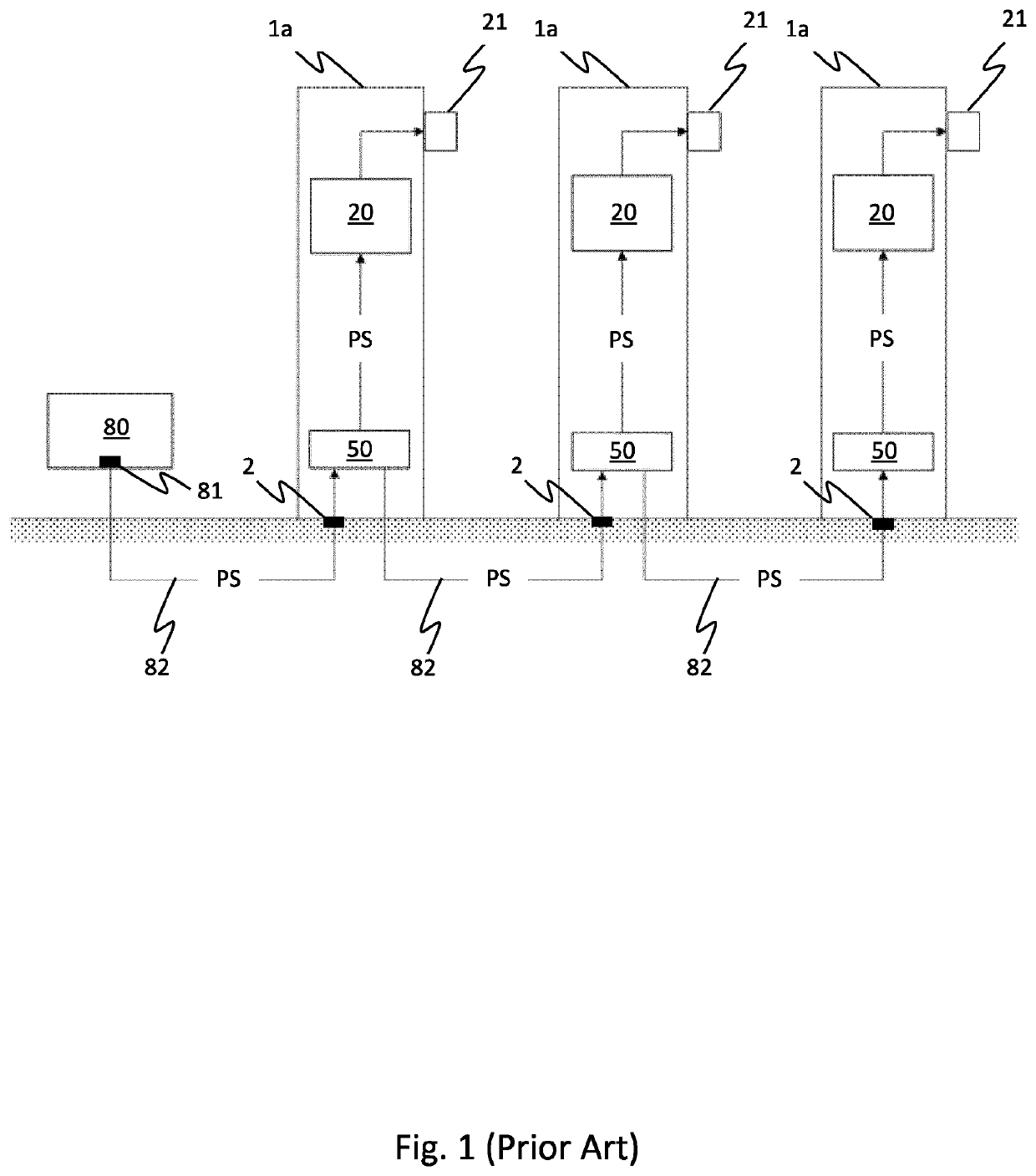
[0055]As described above FIG. 1 shows an example of a typical prior art charging system including several charging fixtures 1a.

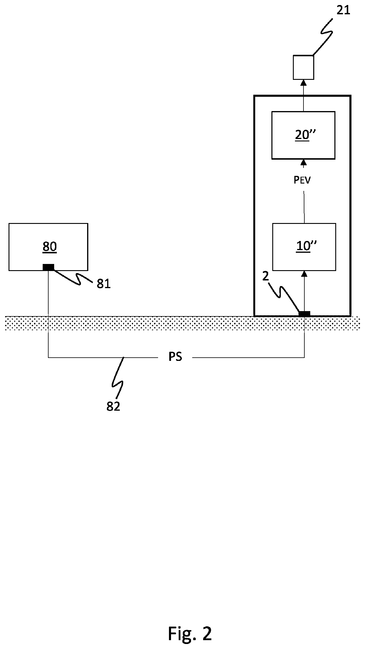
[0056]FIG. 2 shows an embodiment of a charging system in accordance with the invention, comprising one EVSE fixture only. Electric power at voltage level PS is supplied from an external power grid 80, via one or more power inlets 2 of the EVSE fixture, to a fully fixture integrated EVSE (electric vehicle supply equipment) SST (solid state transformer) 10″. The EVSE SST 10″ convert the voltage level from PS at its primary side to a voltage level PEV at its secondary side adapted for charging of batteries in electricity powered vehicles. The converted power is then made available at one or more EV outlets 21 via a dedicated EVSE control device 20″. The latter may perform any modulation, re-routing, switching, etc. considered appropriate / necessary. In addition to the integrated EVSE SST 10″, an external transformer (not shown) may convert the power from the po...


PUM


Abstract

The invention concerns a multipurpose charging system suitable for supplying charging power to an electricity-powered vehicle. The charging system comprises a plurality of spaced apart fixtures, where each fixture comprises a power inlet for receiving electrical energy. At least one of the fixtures is an EVSE fixture comprising a control device system comprising an EVSE control device and an EV plug, where the EVSE control device is configured to charge, via the EV plug, a rechargeable battery powering the electricity-powered vehicle. The energy transfer from the EV plug to the battery may take place via a charging cable. The charging system further comprises a primary power source arranged outside the fixtures for supplying electric energy (PS) to the power inlet of each of the fixtures, one or more second electric loads arranged at least partly within at least one of the fixtures and a solid state transformer system arranged within the at least one EVSE fixture. The solid state transformer system comprises at least an EVSE solid state transformer having a primary side being electrically connectable to the primary power source for receiving electric energy at a voltage level VPS and a secondary side providing electric energy at a voltage level VEVSE, the secondary side being electrically connectable to the EVSE control device, either directly or indirectly.

Description

TECHNICAL FIELD[0001]The present invention relates to a charging system for providing electricity to electricity-powered vehicles and a method for installing such a system. The charging system is particularly adapted for constituting part of a multi-functional charging system for integration into an existing urban infrastructure.BACKGROUND AND PRIOR ART[0002]In recent years there has been a drive towards cleaner vehicles; in particular governments have encouraged the use of electric cars. This is increasingly being achieved through legislations. The tendency is to penalise owners and drivers of larger petrol and diesel vehicles and encourage the use of clean vehicles—such as electric or hybrid vehicles.[0003]The rapid increase in electricity-powered vehicles create however challenges, especially in urban locations such as inner cities. For examples, setting up new charging stations is an expensive exercise, requiring earthwork for cabling and purchase of extensive new infrastructure...

Claims


Application Information

Patent Timeline
IPC IPC(8): B60L53/31B60L53/16B60L53/30B60L53/63
CPCB60L53/305B60L53/16B60L53/63B60L53/31B60L3/0069F21S8/086B60L2270/40Y02T90/14Y04S10/126Y04S30/12Y04S30/14B60L53/30B60L53/665B60L53/18B60L53/68B60L53/67Y02E60/00Y02T10/70Y02T10/7072Y02T90/12Y02T90/167Y02T90/16
Inventor JOHANSEN, BRAGE W.NAESJE, KJETIL
Owner ZAPTEC IP
Why Eureka
Try Eureka