Supercharge Your Innovation With Domain-Expert AI Agents!

Drum brake apparatus

Active Publication Date: 2020-02-20
HYUNDAI MOBIS CO LTD
View PDF15 Cites 5 Cited by
  • Summary
  • Abstract
  • Description
  • Claims
  • Application Information

AI Technical Summary

Benefits of technology

[0020]The main braking part may include: a pair of pistons disposed at ends of the housing, and pressurizing the shoes while moved to the outside of the housin

Problems solved by technology

When the main braking apparatus and the parking braking apparatus are separately manufactured and managed, many inconveniences may arise.
In this case, the productivity may be reduced, and the unit cost may be increased.

Method used


Image

  • Drum brake apparatus
  • Drum brake apparatus
  • Drum brake apparatus

Examples


Embodiment Construction

[0031]Hereafter, a drum brake apparatus in accordance with an embodiment of the present invention will be described in detail with reference to the accompanying drawings. It should be noted that the drawings are not to precise scale and may be exaggerated in thickness of lines or sizes of components for descriptive convenience and clarity only. Furthermore, the terms as used herein are defined by taking functions of the invention into account and can be changed according to the custom or intention of users or operators. Therefore, definition of the terms should be made according to the overall disclosures set forth herein.

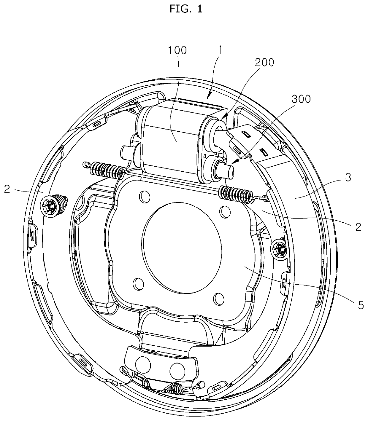
[0032]FIG. 1 is a front perspective view illustrating an installation state of a drum brake apparatus in accordance with an embodiment of the present invention, FIG. 2 is a rear perspective view illustrating the installation state of the drum brake apparatus in accordance with the embodiment of the present invention, and FIG. 3 is a cross-sectional view illustratin...


PUM


Abstract

A drum brake apparatus may include: a housing; a main braking part installed at one side of the housing, and driven by hydraulic pressure to pressurize shoes during main braking; and a parking braking part installed at the other side of the housing, and driven by an electromotive force to pressurize the shoes during parking braking.

Description

CROSS-REFERENCES TO RELATED APPLICATIONS[0001]The present application claims priority to Korean application number 10-2018-0096269, filed on Aug. 17, 2018, which is incorporated by reference in its entirety.BACKGROUND OF THE INVENTION[0002]The present invention relates to a drum brake apparatus, and more particularly, to a drum brake apparatus which generates a braking force through friction with a drum rotating with a wheel.[0003]In general, a drum brake refers to an apparatus that generates a braking force through friction with a drum rotating with a wheel. Specifically, the drum brake acquires a braking force through hydraulic pressure (main braking) or acquires a braking force by rubbing a shoe having a friction material attached thereon against a drum using a cable connected to a parking brake lever (parking braking).[0004]The conventional drum brake includes a drum, a pair of shoes disposed on a back plate so as to face the inner circumferential surface of the drum and having ...

Claims


Application Information

Patent Timeline
IPC IPC(8): F16D51/24F16D51/22B60T1/06F16D65/22
CPCF16D51/22F16D2125/40F16D65/22F16D2051/005F16D2125/06F16D2051/003F16D51/24F16D2121/04F16D2125/52F16D2121/24B60T1/067F16D65/06F16D65/16B60T13/588B60T13/741F16D65/44F16D2500/50233
Inventor CHOI, MOO JIN
Owner HYUNDAI MOBIS CO LTD
Features
  • R&D
  • Intellectual Property
  • Life Sciences
  • Materials
  • Tech Scout
  • Unparalleled Data Quality
  • Higher Quality Content
  • 60% Fewer Hallucinations
Learn More