Brake cable connecting apparatus for drum brake

a technology of brake cable and connecting apparatus, which is applied in the direction of mechanical apparatus, brake system, transportation and packaging, etc., can solve the problems of low durability and noise of intensive impact, and achieve the effect of facilitating the mounting work of resilient, facilitating the disengaging of brake cable, and facilitating the mounting work

Inactive Publication Date: 2004-03-25
AH BRAKE CO LTD
View PDF6 Cites 17 Cited by
  • Summary
  • Abstract
  • Description
  • Claims
  • Application Information

AI Technical Summary

Benefits of technology

[0012] For the purpose of effectuating a braking force, the brake shoes need to rotate so as to fill up the clearance on either side, depending upon the rotational direction of the brake drum. Therefore, a higher impact load is applied to the anchor, thereby giving lower durability and causing an intensive impact noise.
[0026] This disclosure facilitates disengaging the brake cable from the brake lever. The resilient member can be deformed as a result of only operating the operating portion. Therefore, the brake cable can be taken away from the brake lever.

Problems solved by technology

Therefore, a higher impact load is applied to the anchor, thereby giving lower durability and causing an intensive impact noise.

Method used


Image

  • Brake cable connecting apparatus for drum brake
  • Brake cable connecting apparatus for drum brake
  • Brake cable connecting apparatus for drum brake

Examples


example 1

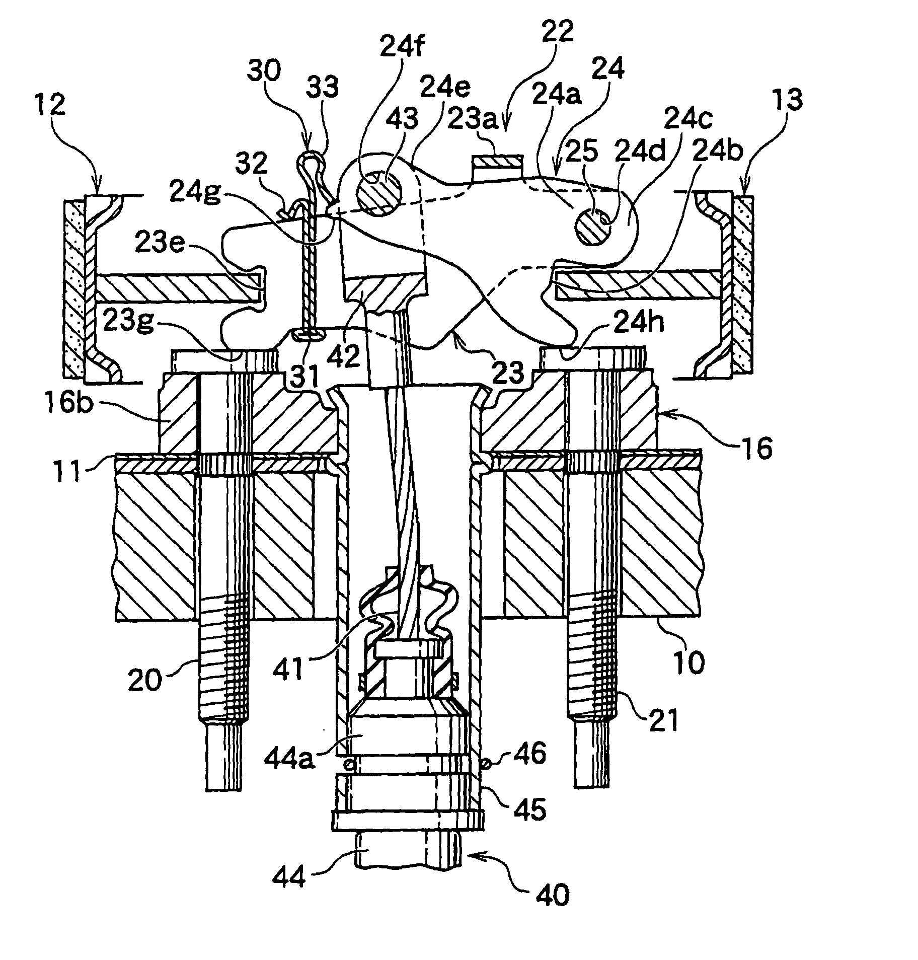
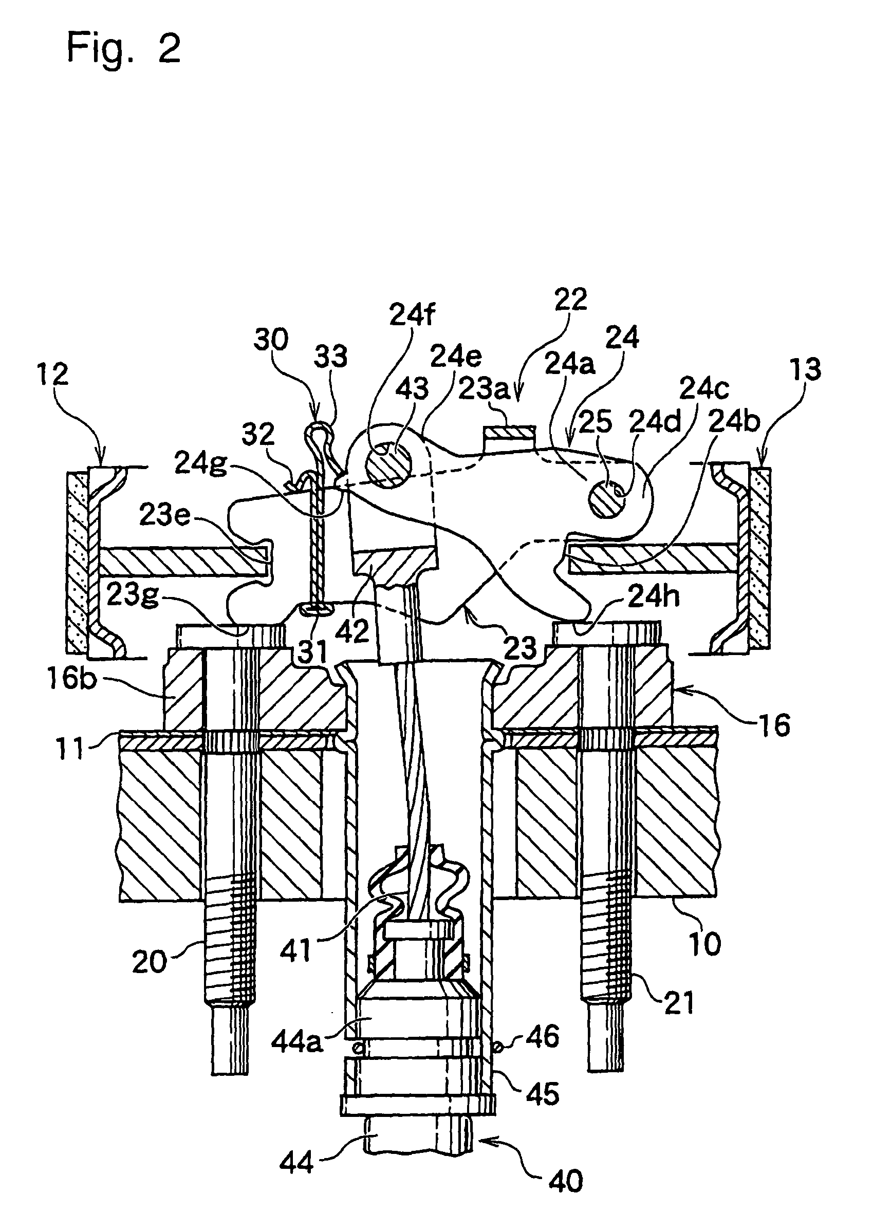
[0041] Example 1 of this invention will be explained with reference to FIGS. 1-6.

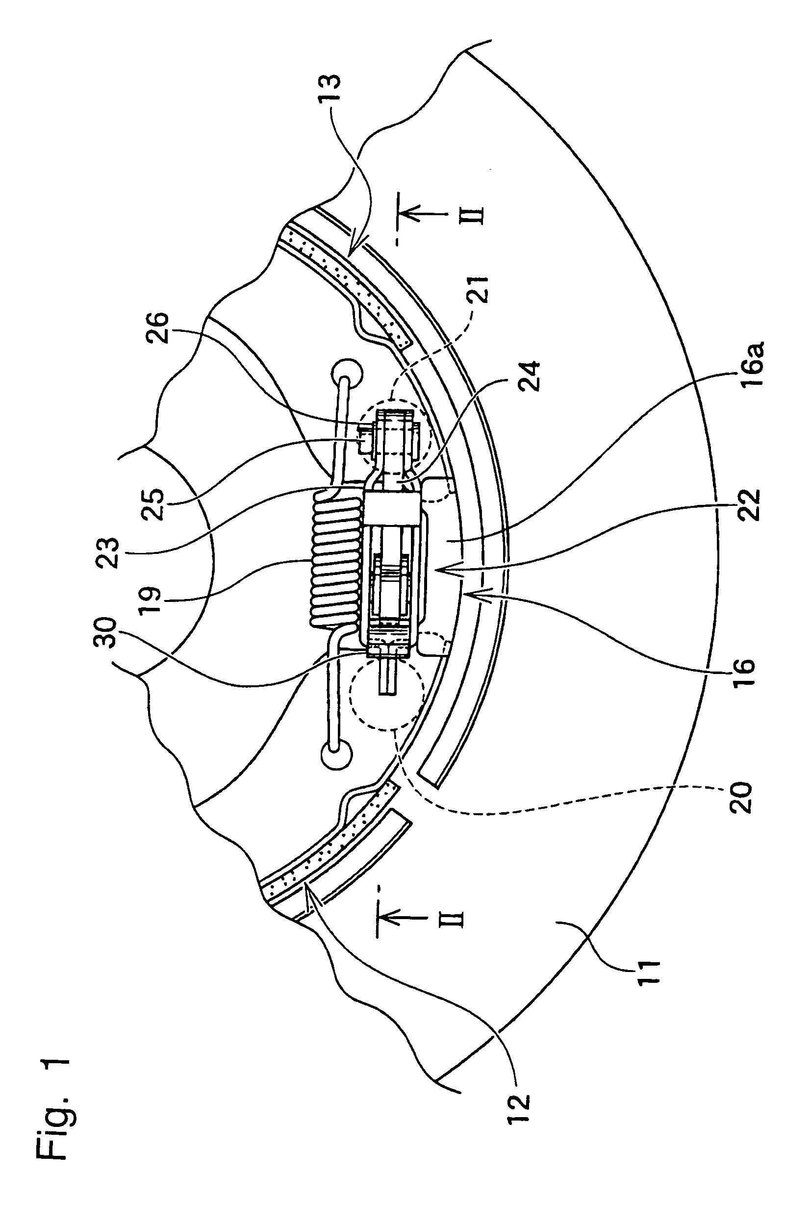
[0042] Terms, "upper" and "lower" and "right" and "left" in this example are explained with reference to FIG. 1 unless specifically stated otherwise.

[0043] A pair of brake shoes 12 and 13 is moveably supported on a back plate 11 fixed to a stationary part 10 of a vehicle body by a shoe hold mechanism (not shown in the figures). Lower ends of the brake shoes are supported by a wall portion 16a of an anchor 16 and upper adjacent end thereof (not shown in the figures) are connected by a connecting mechanism (not shown in the figures). One shoe return spring (not shown in the figures) is extended between the upper ends of the brake shoes 12 and 13, which maintains an abutment between the connecting mechanism and the upper ends of the brake shoes 12, 13, while lower shoe return spring 19 is extended between the lower ends of the brake shoes 12 and 13, which maintains an abutment between the lower ends of the...


PUM


Abstract

A brake cable connecting apparatus ensures prevention of brake cable disengagement by a simple structure that offers simple and accurate assemblability. The brake cable connecting apparatus comprises the strut 23 engaging with the brake shoe 12 and the plate-like brake lever engaging with the brake shoe 13. The proximal portion 24a of the brake lever 24 is pivotally positioned in the wider space 23c formed between the two facing surface walls of the strut 23. The cable end 42 of the brake cable 40 is connected with the free end 24e of the brake lever 24 by the connecting pin 43. The inner cable 41 is operated to effectuate braking, and the projection 24g of the free end 24e interferes with the resilient stopper 33 of the resilient member 30 mounted on the strut 23 and is positioned on the rotating trajection of the brake lever 24.

Description

[0001] 1. Field of the Invention[0002] This invention relates to a mechanical shoe expander and more particularly to a brake cable connecting apparatus for connecting a brake cable with a mechanical operating mechanism mainly comprised of a strut and a brake lever.[0003] 2. Description of Conventional Arts[0004] A typical brake cable connecting apparatus comprises a mechanical actuator having a strut, a plate-like brake lever which is retained in the strut and which is pivotally mounted on the strut, and a pivot pin.[0005] The mechanical actuator is positioned between a pair of brake shoes and then the strut and the brake lever as components of the mechanical actuator engage with the corresponding brake shoes. When the brake cable connected with the brake lever is operated in a cable operating direction, the brake lever rotates about a pivotally supported point with the strut. Therefore the engaging part of the strut against one brake shoe and the engaging part of the brake lever ag...

Claims


Application Information

Patent Timeline
Patent Type & Authority Applications(United States)
IPC IPC(8): B60T11/04F16D51/22F16D65/14F16D65/22F16D65/28
CPCB60T11/046F16D65/22F16D2125/64F16D2125/62F16D2121/14
Inventor TATSUMI, YOSHIHIROIKEDA, TAKASHIFUJIYAMA, MASAMI
Owner AH BRAKE CO LTD
Why Eureka
Try Eureka