Light transmission element, optical receiving unit, optical actuator unit, lidar system, working device and vehicle

Active Publication Date: 2020-02-20
ROBERT BOSCH GMBH
View PDF0 Cites 0 Cited by
  • Summary
  • Abstract
  • Description
  • Claims
  • Application Information

AI Technical Summary

Benefits of technology

[0003]The light transmission element according to the present invention having the features described herein has the advantage that an optical arrangement may be achieved in a beam path using a simple arrangement and an angle adaptation of transmitted light, or of electromagnetic radiation in general, may be achieved in a particularly loss-free manner. According to the present invention, this is achieved by the features described herein in that a light transmission element is created, and in particular for an optical unit or of an optical unit and, in particular, for an optical receiving unit or for an optical emission or actuator unit for transmission and, in the process, angle adaptation of transmitted electromagnetic radiation and, in particular, of light and/or infrared radiation. The light transmission element is configured and situated in the form of a layer and includes a sequence of a multitude of optical elements. The layer includes a first side or

Problems solved by technology

Conversely, this means that, under unfavorable circumstances, i.e., in the case of large angles of incidence in comparison to the axis of incidence, the filter properties may deviate from the setpoint values.
In other optical applications as well, large angles of incidence in

Method used


Image

  • Light transmission element, optical receiving unit, optical actuator unit, lidar system, working device and vehicle
  • Light transmission element, optical receiving unit, optical actuator unit, lidar system, working device and vehicle
  • Light transmission element, optical receiving unit, optical actuator unit, lidar system, working device and vehicle

Examples


Example

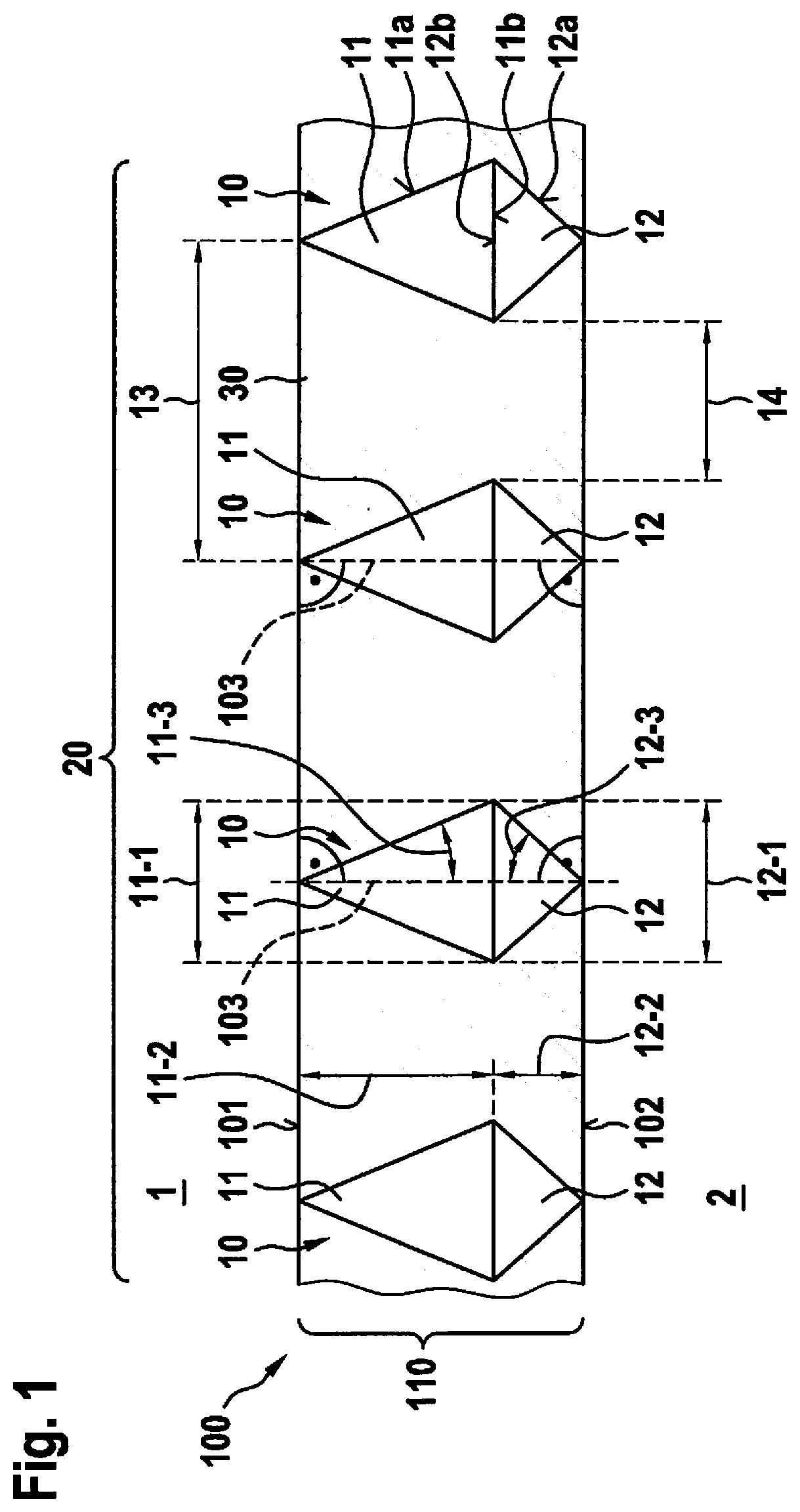
[0040]FIG. 1 shows a schematic side view of a first specific embodiment of the light transmission element 100 according to the present invention.

[0041]Light transmission element 100 according to FIG. 1 configured according to the present invention is made up of an arrangement 20 of a multitude of optical elements 10, which are configured in the form of a double pyramid or a double cone and are thus made up of a first subelement 11 including a base 11b and a jacket 11a, and a second subelement 12 including a base 12b and a jacket 12a, which have identical bases 11b and 12b and which face one another and, in particular, are connected to one another with their bases 11b, 12b.

[0042]Optical elements 10 are situated in one plane, essentially form a layer 110, and divide the entire space into a first or upper half-space or a first or upper side 1, and into a second or lower half-space or a second or lower side 2. A first or upper side 101 of layer 110 faces the first half-space or first s...


PUM


Abstract

A light transmission element for an optical unit for transmitting and, in the process, adapting the angle of transmitted light, including a sequence of a multitude of optical elements situated in the form of a layer, in which the layer forms a first side and a second side, which face away from one another, a respective optical element including a pair of subelements, which each extend from a geometrically essentially identical base in a tapering manner and which face one another with their bases and extend with different lengths along their taper, and the optical elements being aligned in such a way that subelements having a greater length face the first side and subelements having a lesser length face the second side.

Description

FIELD OF THE INVENTION[0001]The present invention relates to a light transmission element for an optical unit, to an optical receiving or actuator unit, to a LIDAR system, and to a working device and, in particular, to a vehicle.BACKGROUND INFORMATION[0002]In many technical applications, wavelength filters are used in optical receiving units or also in emitters, provided upstream in the optical path, to limit the spectrum to be received or to be emitted. It is known that such wavelength filters frequently have a transmission window dependent on the actual angle of incidence of the radiation with respect to the position and width of the window in the spectrum. Conversely, this means that, under unfavorable circumstances, i.e., in the case of large angles of incidence in comparison to the axis of incidence, the filter properties may deviate from the setpoint values. In other optical applications as well, large angles of incidence in relation to the axis of incidence result in an undes...

Claims


Application Information

Patent Timeline
IPC IPC(8): G01S7/486G01S17/06G02B19/00
CPCG01S17/06G02B19/0019G01S7/486G01S17/42
Inventor HOLLECZEK, ANNEMARIEKAMIL, MUSTAFA
Owner ROBERT BOSCH GMBH
Why Eureka
Try Eureka