
Cleaning device, and image capturing apparatus including cleaning device

a cleaning device and cleaning technology, applied in vehicle maintenance, vehicle cleaning, instruments, etc., can solve the problems of excessive cleaning process, insufficient cleaning of translucent bodies, inconvenience of excessive cleaning, etc., and achieve the effect of reducing or preventing excessive cleaning or insufficient cleaning

Active Publication Date: 2020-02-20
MURATA MFG CO LTD
View PDF6 Cites 9 Cited by
  • Summary
  • Abstract
  • Description
  • Claims
  • Application Information

AI Technical Summary

Benefits of technology

The present invention provides cleaning devices that can adjust the level of cleaning based on the amount and condition of adherents on a translucent body. The controller analyzes the electrical characteristics of the body and adjusts the cleaning level accordingly to prevent excessive or insufficient cleaning. This results in improved cleaning efficiency.

Problems solved by technology

However, the cleaning device described in Japanese Unexamined Patent Application Publication No. 2015-057338 only has the function of cleaning a translucent body by discharging cleaning solution from an opening portion of a nozzle to the surface of the translucent body, and performs the same cleaning process regardless of the amount and condition of adherents (dirt) on the translucent body.
Therefore, with the cleaning device described in Japanese Unexamined Patent Application Publication No. 2015-057338, when the cleaning process is set for a state where the amount and condition of adherents on the translucent body is severe, there is an inconvenience that the cleaning process is excessively performed even in a state where the amount and condition of adherents on the translucent body is light, with the result of unnecessary discharge of cleaning solution or unnecessary consumption of electric power.
In addition, with the cleaning device described in Japanese Unexamined Patent Application Publication No. 2015-057338, when the cleaning process is set for a state where the amount and condition of adherents on the translucent body is light, there is an inconvenience that the translucent body is not sufficiently cleaned when the amount and condition of adherents on the translucent body is severe.

Method used


Image

  • Cleaning device, and image capturing apparatus including cleaning device
  • Cleaning device, and image capturing apparatus including cleaning device
  • Cleaning device, and image capturing apparatus including cleaning device

Examples


first preferred embodiment

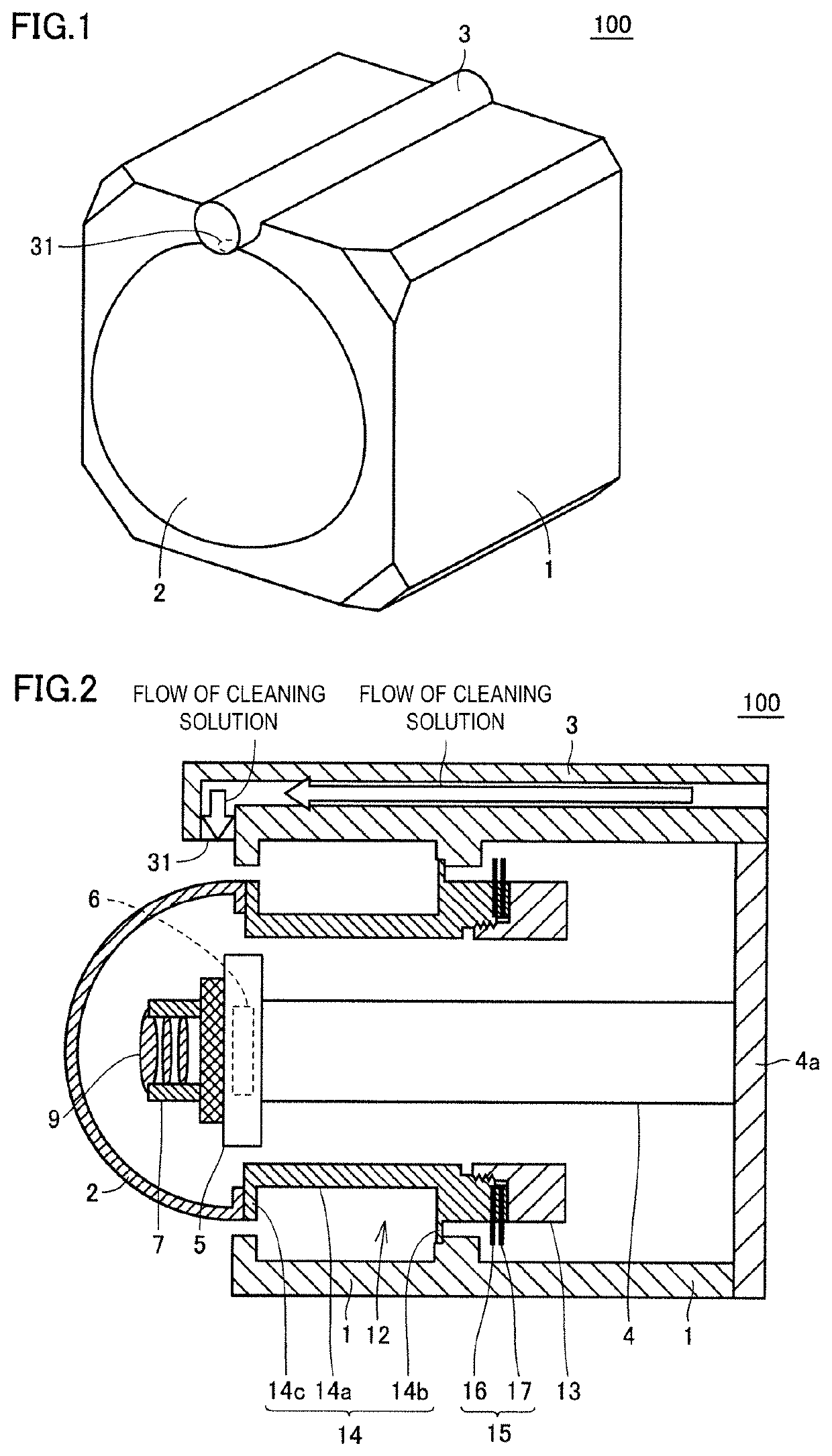
[0021]An image capturing apparatus according to a first preferred embodiment of the present invention will be described with reference to the drawings. FIG. 1 is a perspective view showing the configuration of the image capturing apparatus 100 according to the first preferred embodiment of the present invention. FIG. 2 is a cross-sectional view showing the configuration of the image capturing apparatus 100 according to the first preferred embodiment of the present invention. The image capturing apparatus 100 includes a casing 1, a translucent protective cover 2 provided at one side of the casing 1, a cleaning nozzle 3 including an opening portion 31 to discharge cleaning solution to the protective cover 2, a vibrator 12 that causes the protective cover 2 to vibrate, and an image capturing device 5 provided inside the protective cover 2. The components, that is, the casing 1, the protective cover 2, the cleaning nozzle 3, and the vibrator 12 of the image capturing apparatus 100, othe...

second preferred embodiment

[0067]In the cleaning device according to the first preferred embodiment, the controller 20 just controls the level of vibrations of the vibrator 12 according to the amount and condition of adherents on the protective cover 2. In a cleaning device according to the present preferred embodiment, a configuration of executing control to clean with a cleaning solution discharged from the cleaning nozzle other than vibrations of the vibrator 12 according to the amount and condition of adherents on the protective cover 2 will be described.

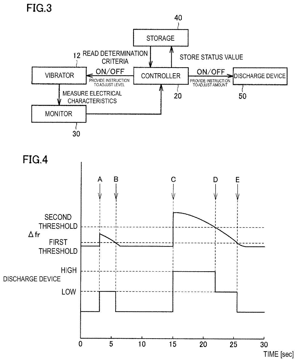
[0068]FIG. 6 is a timing chart for illustrating control of the cleaning device of an image capturing apparatus according to the second preferred embodiment of the present invention. In the timing chart shown in FIG. 6, the top row shows the waveform of a differential value Δfr obtained by subtracting the frequency f0 that is an initial value from the resonant frequency fr read from the monitor 30, the middle row shows the waveform to provide an instructio...

third preferred embodiment

[0086]In the cleaning device according to the first preferred embodiment, the case where the determination criteria are determination criteria of the same type like the first threshold with which the electrical characteristic value detected by the monitor 30 is compared, and the second threshold different from the first threshold, is described. In a cleaning device according to the present preferred embodiment, the case where the determination criteria are different types will be described.

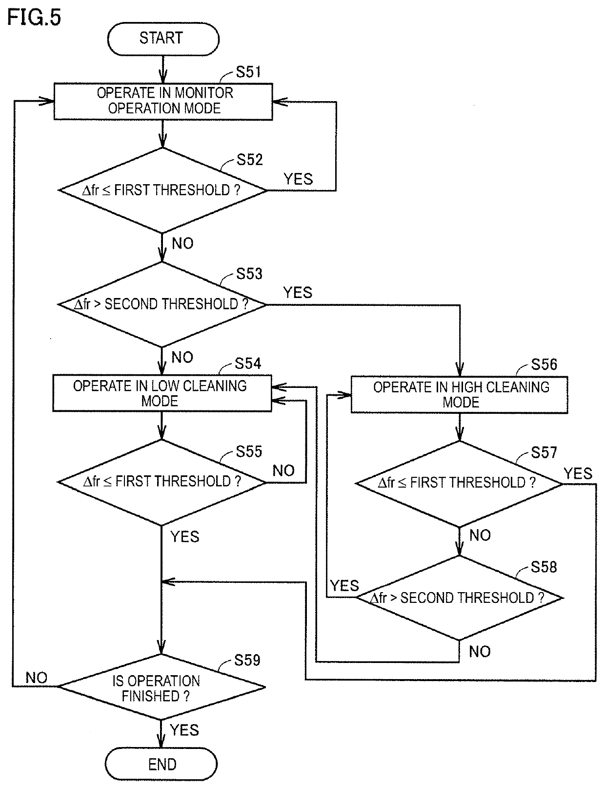
[0087]It is assumed that the determination criteria according to the present preferred embodiment are determination criteria of different types such as a threshold with which the electrical characteristic value detected by the monitor 30 is compared, and a duration of control. FIG. 8 is a flowchart for illustrating control of the cleaning device of an image capturing apparatus according to the third preferred embodiment of the present invention. First, the controller 20 operates the vibrator 12 in...


PUM


Abstract

A cleaning device includes a casing holding an image capturing device, a protective cover disposed in a visual field of the image capturing device, a vibrator to vibrate the protective cover, a controller to control the vibrator, a monitor to detect an electrical characteristic value associated with a vibration of the vibrator, and a storage to store determination criteria based on which the controller evaluates the electrical characteristic value detected by the monitor. The controller is configured to evaluate the electrical characteristic value based on the plurality of determination criteria stored in the storage and clean a surface of the translucent body by controlling the vibrator according to the determination.

Description

CROSS REFERENCE TO RELATED APPLICATIONS[0001]This application claims the benefit of priority to Japanese Patent Application No. 2017-087230 filed on Apr. 26, 2017 and is a Continuation Application of PCT Application No. PCT / JP2018 / 003383 filed on Feb. 1, 2018. The entire contents of each application are hereby incorporated herein by reference.BACKGROUND OF THE INVENTION1. Field of the Invention[0002]The present invention relates to a cleaning device, and an image capturing apparatus including a cleaning device.2. Description of the Related Art[0003]An image capturing apparatus has been provided at the front or rear of a vehicle and images captured by the image capturing apparatus are used as images or the like for navigation. Such an image capturing apparatus is provided outside a vehicle, so foreign matter, such as raindrops, mud, and dust, can adhere to a translucent body (lens or protective glass) that covers the outer portion of the image capturing apparatus. When foreign matter...

Claims


Application Information

Patent Timeline
Patent Type & Authority Applications(United States)
IPC IPC(8): G02B27/00B08B7/02
CPCB08B7/02G02B27/0006B60S1/56B60R11/04B60R2011/004G03B17/08G02B7/021H04N23/811H04N23/52
Inventor KURATANI, YASUHIROFUJIMOTO, KATSUMINISHIYAMA, KENJIHORIGUCHI, CHIKAHIROICHIGUCHI, SHINICHIROTAKATA, MASAAKIMIZUSHIMA, YUZOISHII, YUUKI
Owner MURATA MFG CO LTD
Learn More